Drawing customizations panel
The Drawing Customizations panel allows you to create custom templates for drawings.
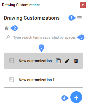
- Menu
- Home
- Search
- Add customization
- Customizations List
Menu
- Refresh
- Refreshes the Drawing Customizations panel.
- Manage libraries
- Opens the Settings dialog box to change the section settings search path.
- Load customizations
- Allows you to choose a folder that contains customizations.
Home
Moves the cursor to the main user interface page of the panel.
Search
Searches all the drawing customizations that matches the words you enter in the search box.
Add customization
Creates a new template.
You can create a template by clicking on the  button. By default,
the template is named New Customization with the text highlighted. After you
have added a relevant name for the template, press Enter to save and apply the
changes. The inserted customizations will be sorted alphabetically automatically.
Use the scroll button to navigate through the list.
button. By default,
the template is named New Customization with the text highlighted. After you
have added a relevant name for the template, press Enter to save and apply the
changes. The inserted customizations will be sorted alphabetically automatically.
Use the scroll button to navigate through the list.
Customizations List
Displays all the available drawing customizations.
- Duplicate
- Creates a copy of your selected drawing customization.
- Rename
- Edits the name while the text is being highlighted. Press Enter to save and apply the changes.
- Delete
- Removes the drawing customization. The Removing a drawing customization dialog box appears.
- Entity customizations
-
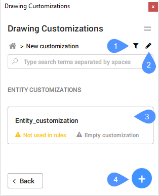
Entity Customizations refer to the visibility settings of how you would like to have your elements in your model drawing to look like.
The Entity customizations list is empty for a newly created customization.
To create an entity customization left-click on the desired template, then click on the
button. By default, the template is named New
Customization with the text highlighted. Rename it
while the text is being highlighted. Press Enter to save and apply
the changes.After creating your desired entity customization templates, click on the individual tabs to modify their respective settings.
- To rule definitions
- To style definitions
- Entity customizations list
- Add customization
- To rule definitions
-
You can create a rule pressing the
button. After creating the rule, the
button offers you another 3 options:
- Entity customization
- Sub rule
- Filter
When creating an entity customization, you can add a sub rule for a rule already added.
- To style definitions
-
To add a style definition, press the
button.When selecting a color, the Select Color dialog box will appear.
When selecting a line type and pressing Load…, the Load Linetypes dialog box will appear.
- Entity customizations list
- Displays the list of entity customizations.
- Add customization
-
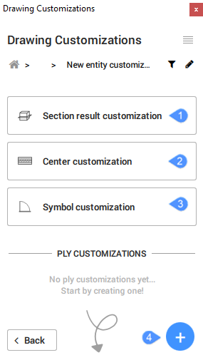
- Section result customization
- Center customization
- Symbol customization
- Add ply customization
- Section result customization
-
Determines how the different pieces of geometry, generated by sectioning the entity with a section plane, are displayed.
- Physical Materials
- Physical Materials
- Opens the Physical Materials dialog box.
- Center customization
- Determines the appearance of the center of planar entities (center plane) or linear entities (center line).
- Symbol customization
-
Determines the appearance of 2D symbols that are added for the entity and controls the source of those symbols.
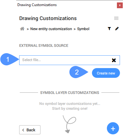
- Select file…
- Create new
- Select file…
- Opens the Set external symbol source dialog box.
- Create new
-
Opens the New external symbol source dialog box.
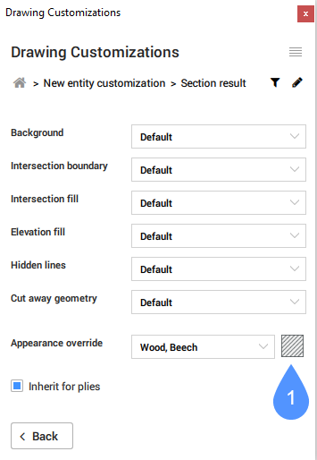
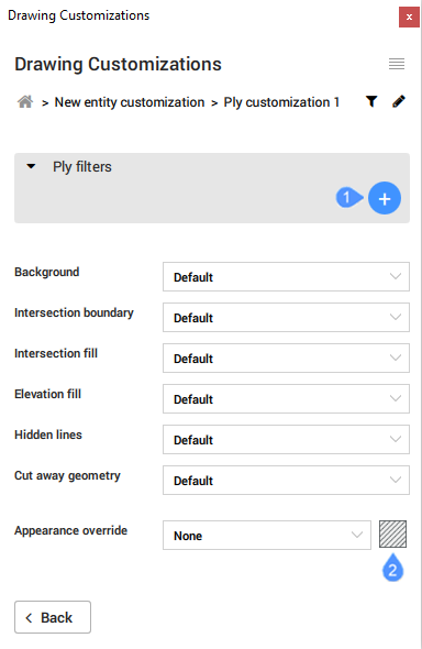
The section result customization and center customization display a series of controls for which you can choose values from the drop-down list.
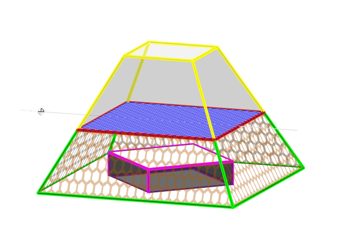
The diagram above illustrates how you could control the visibility and customization settings of an entity with the Drawing Customization tool. Notice that the section plane is aligned with the Blue square with Red outline.
- Green outline represents Background, which is essentially the elevation outline of the cut object.
- Red outline represents Intersection Boundary, which traces over the cut area.
- Blue hatch represents Intersection Fill, as it shows the area of being cut by the section plane.
- Orange hexagons hatch represents Elevation Fill, which refers to the area bound by the elevation outline (see Background).
- Pink outline represents Hidden Lines, as it is below the blue hatch.
- Yellow outline represents Cut away geometry, as it is above the section plane.
Appearance Override allows you to specify how an entity's hatch appearances (section and elevation) would appear, in place of the default hatch patterns already defined within the Physical Materials library. When you create any new Physical Material entry in the "In Project" category as part of the Drawing Customization template, your desired configurations are independent of the drawing project and stored in the template instead. You can later apply this template to other project models as you wish.
- Add ply customization
-
To add a ply customization, press the
button.
- Add default function
- Physical Materials
- Add default function
- Adds a default function for the ply customization.
- Physical Materials
- Opens the Physical Materials dialog box.