Connecting solids
Commands
LCONNECT, TCONNECT, BIMSTRUCTURALCONNECT
About
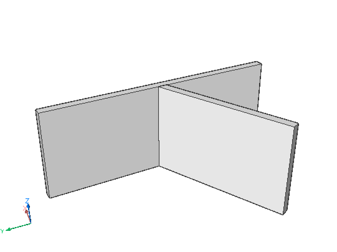
The LCONNECT command creates an L-connection (bisector or parallel) between two solids.
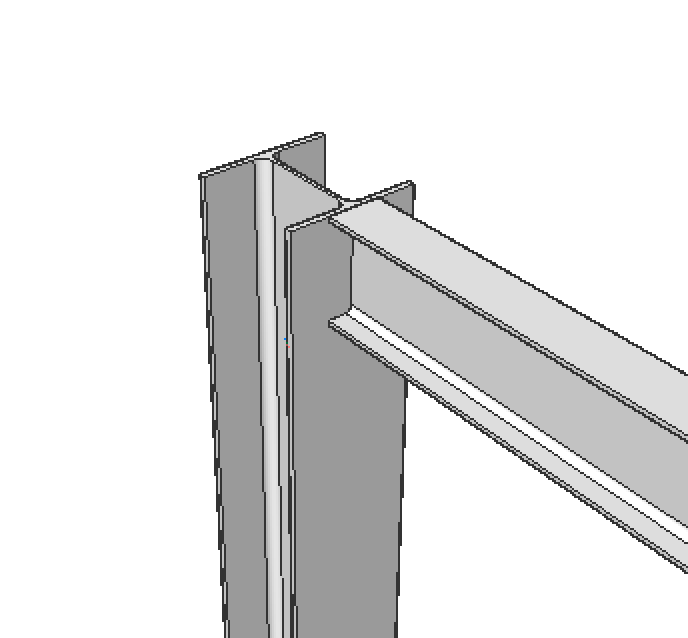
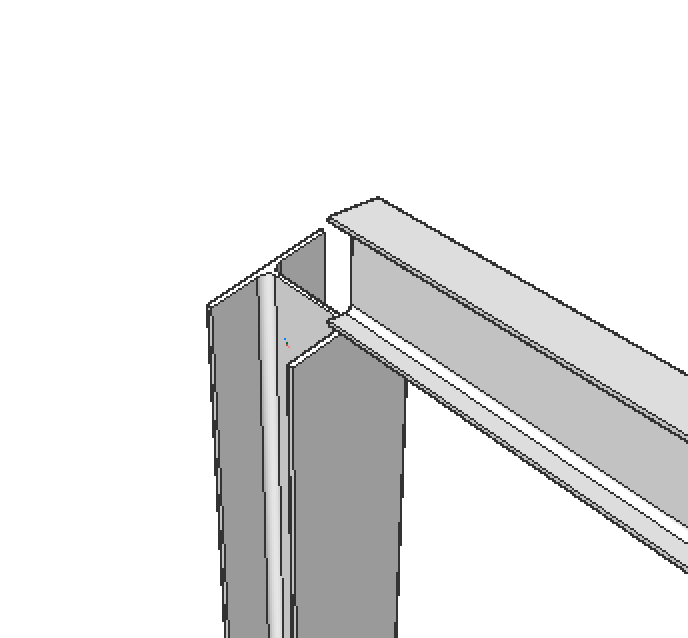
The TCONNECT command creates a T-connection between two solids.
The BIMSTRUCTURALCONNECT command connects structural profile solids such as beams and columns.
The BIMFLOWCONNECT command creates a connection between flow segments, such as pipes or HVAC ducts.
The procedures below use the Quad cursor menu.
Procedure: creating L-connections
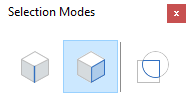
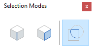
- Make sure SELECTIONMODES system variable = 0.
- Type LConnect in the Command line or select it via the Quad.
- Select two solids or faces to connect.
- The two selected solids are connected: the default connection type is
L-bisector.If HOTKEYASSISTANT system variable is ON (HKA is switched on), the Hotkey Assistant widget displays.

Use the CTRL key to cycle between the connection types or
You are prompted: Select base solid [Switch] <Accept>. Type Ato use the selected connection, type S to switch to the desired connection type.
The 3D model updates dynamically when cycling the L-connection types.Note: L-connections can also be created between non-vertical solids such as roof slabs.
Procedure: Creating T-connections
- Make sure the Select Faces option of the
SELECTIONMODES system variable is selected.
- Type TCONNECT in the Command line or select it via the Quad.
- Move the cursor over the minor face of the first solid at the end that needs
to be connected.
Press Tab to highlight obscured faces.
Click when the face highlights.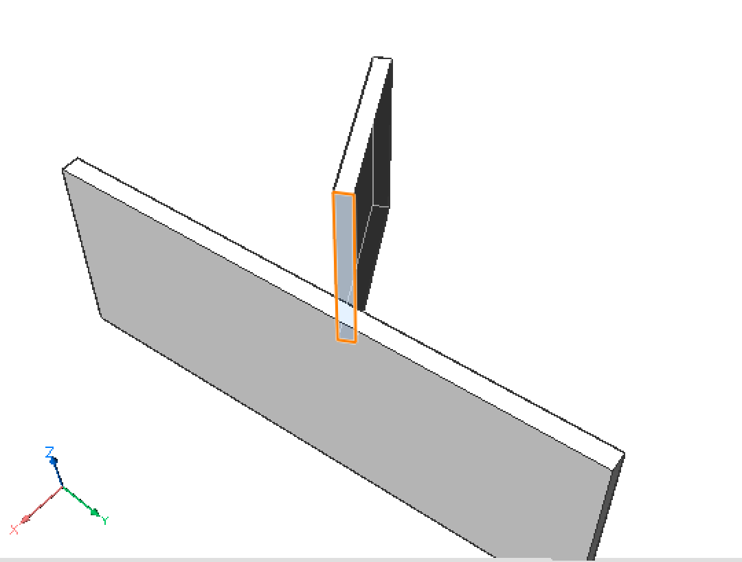
- (Optional) Repeat the previous step to select more faces, then press
Enter.Tip: The SELECTALIGNEDFACES command in the Select command group in the Quad selects all faces in the 3D model that are in the same plane (coplanar) with a selected face.
- You are prompted: Select entities to connect to or [Connect to nearest/Disconnect/selection options (?)] <Connect to nearest>:
- Do one of the following:
- Press Enter to connect to the nearest face(s).
- Select one or more faces.
If necessary, press Tab to highlight an obscured face; click when the face is highlighted.
Right click to stop selecting faces.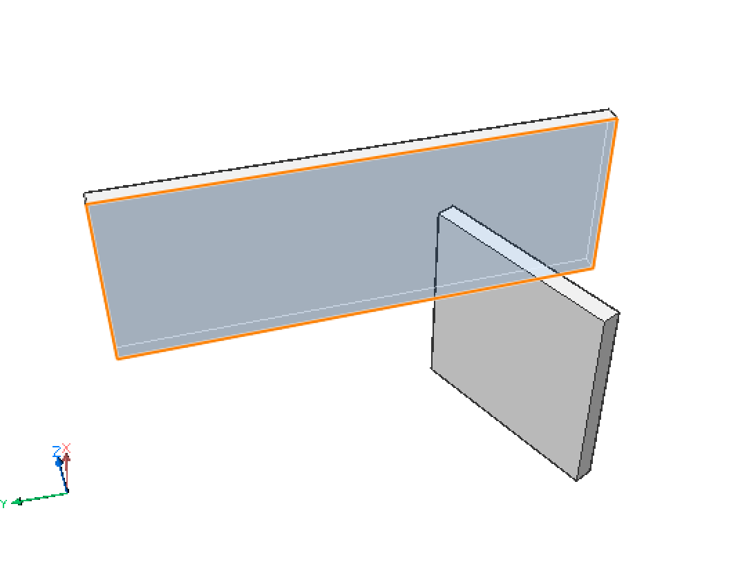
Tip: Hover over the minor face of the solid and choose Connect with Nearest in the Model command group of the Quad.
 |
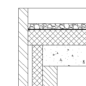 |
| 3DModel | Calculated Section |
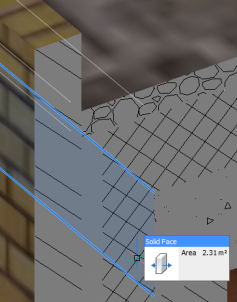
To control the connection of composition plies between two building elements, you can Push/Pull a ply in a clipped BimSection (if Show Composition is ON). For more in-depth information, visit the BIM Ply Editing article.
- Place the cursor over the face of the ply you want to connect. If necessary, repeatedly press Tab to select an obscured face.
- When the ply face highlights, choose Push/Pull in the Quad.
- Specify to which point the selected ply should reach by moving the cursor or typing in the distance.
- Right-click or press Enter to confirm.
The ply of the first solid is connected to the ply of the second solid. The connected ply is subtracted from the second solid.
- Optionally, use the BIMPROPAGATEPLANAR command to apply the connection to similar locations in the model.
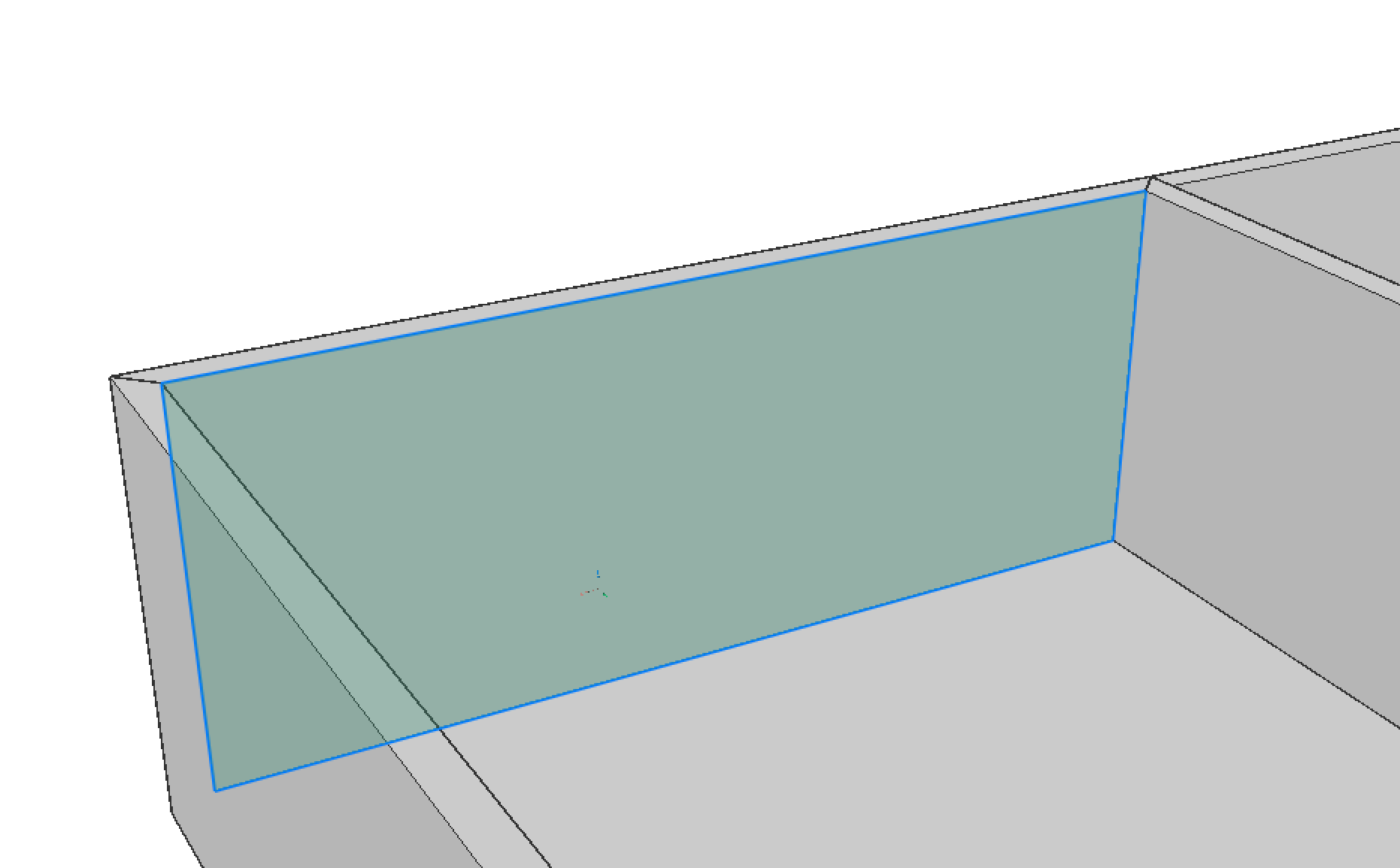
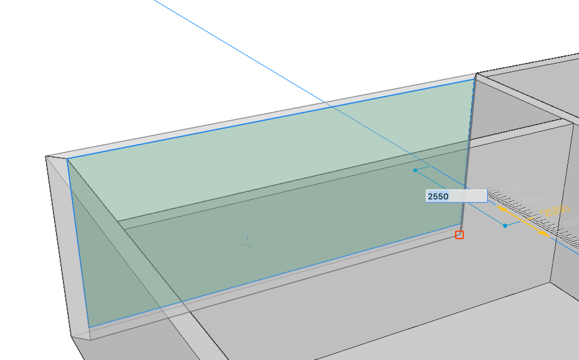
Procedure: Setting the distance between parallel solids
- Select the solid of which the position must be fixed.
- Select the solid which will be moved when defining the new distance.
The nearest distance between the solids displays.
- Type a value in the distance field and press Enter.
Procedure: Creating a copy of a solid
- Make sure the Select Faces option of the
SELECTIONMODES system variable is selected.
- Move the cursor over a face of the solid to be copied.
- When the face highlights, choose BimCopy in the
Model command group of the Quad.
A copy of the solid displays dynamically. The ruler indicates the current distance.
- Type a value in the dynamic entry field and press Enter.
- Make sure the Enable boundary detection option of the
SELECTIONMODES system variable is selected.
- Highlight the part of the boundary for the part of the solid you want to
copy.
- When the face highlights, choose BimCopy in the
BIM command group of the Quad.
A partial copy of the solid displays dynamically. The ruler indicates the current distance.
- Type a value in the dynamic entry field and press Enter.
Procedure: disconnecting two connected solids
In some cases, you need to disconnect 2 solids of a node to do some further direct modeling.
- Type LCONNECT in the Command line.
- Select the two solids.
- The connection is automatically made, press CTRL until the disconnect icon is
highlighted.

- Press Enter.
Note: You can use Propagate to disconnect similar nodes.