In BricsCAD, the Window Creator tool allows you to turn a
different set of design ideas into a window. You can use the tool on windows of all
shapes and sizes, which enables you to utilize a significant amount of window styles
in your BIM project.
When you have a closed 2D entity or boundary on the face of a solid (wall), the
window creator tool enables you to use these closed entities to make your window.
Using the window creator tool, you can select any window styles in the dialog box
and change the properties of this created window in a BIM model.
Creating a parametric window using boundaries
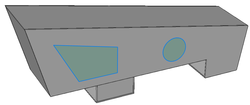
Draw a polygon on the face of a solid (wall).
Based on this base profile,
the window opening will be created.
Make sure Boundary Detection (select detected
boundaries) is enabled into SELECTIONMODES system variable. Hover over the
inside of the polygon and select the Create Window
tool from the Quad.
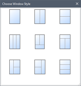
A Choose Window Style dialog box
displays:
Select a window style in the dialog box.
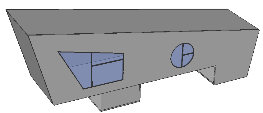
The window is created on the
wall with the selected style. The following illustration shows the
triple panel left window style which was selected to create the windows
on the face of the wall.
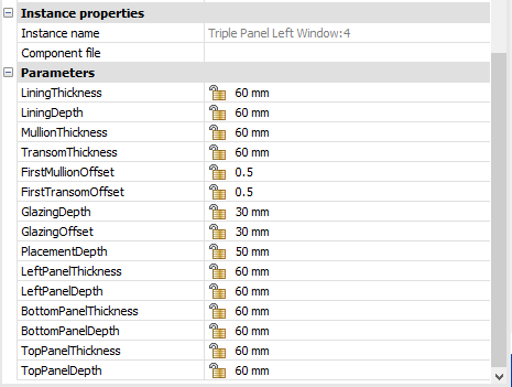
(Optional) You can refine the window design by changing the default
values of the parameters. To do this, select the window and change the
desired parameters in the Properties panel.
To change one of the default parameters of this window, type a new
value in the property field.
Press Enter to accept the new value
of the parameter. The window should be updated automatically.
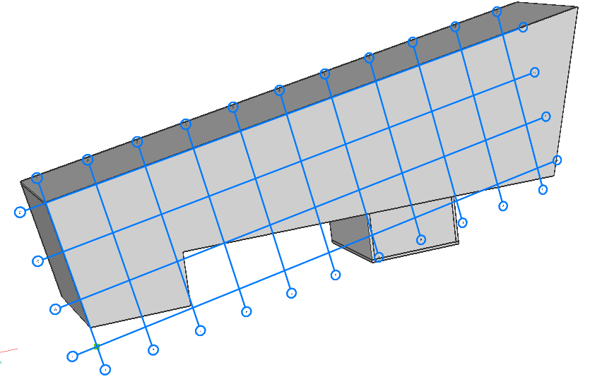
Create windows based on a grid
Use BIMGRID command to create a Grid on the face of the wall. Choose the
basic dimensions in the Command line. Changing the
U-line and V-line panel
options allows you to specify the desired size and number of panels on the
surface.
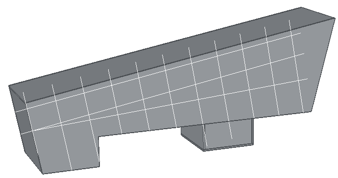
Note: To draw on the face, make sure you
first highlight the face and then click. Otherwise, the Grid will be
created in the XY-plane.
Use BEDIT or REFEDIT to edit the Grid.
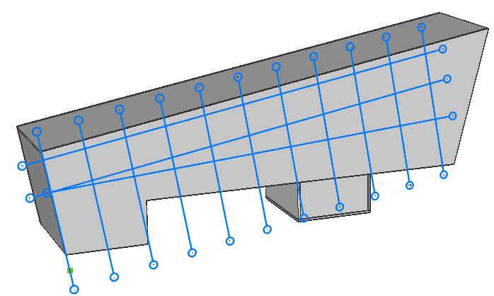
Use the Manipulator to change the
position of the gridlines on the wall.
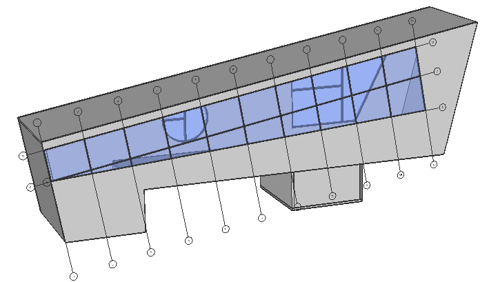
Select the Grid and select Create Window in the
Quad.
The window is generated based on the gridlines.
Note: You can edit the parameters in the
Properties panel. Type a new value in the
property field and press Enter. The window will automatically update
itself.
Creating window openings
BIM Opening Create creates an opening without window geometry.
It uses the same command as BIMWINDOWCREATE. The command allows to create an opening
at the location of the selected base profile. The base profile can be a boundary or
a closed polyline.
For more information about this command, visit the Command Reference article
BIMWINDOWCREATE.
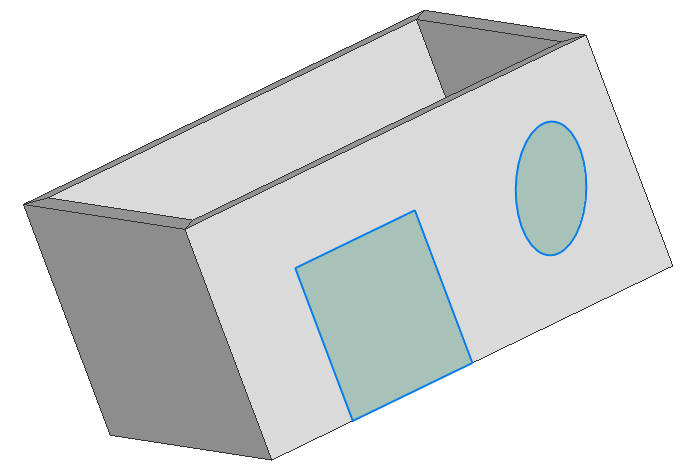
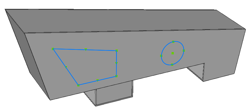
Draw one or more closed polylines on the face of a wall.
While boundary detection is on, hover over the polygon.
Or select the
closed polyline.
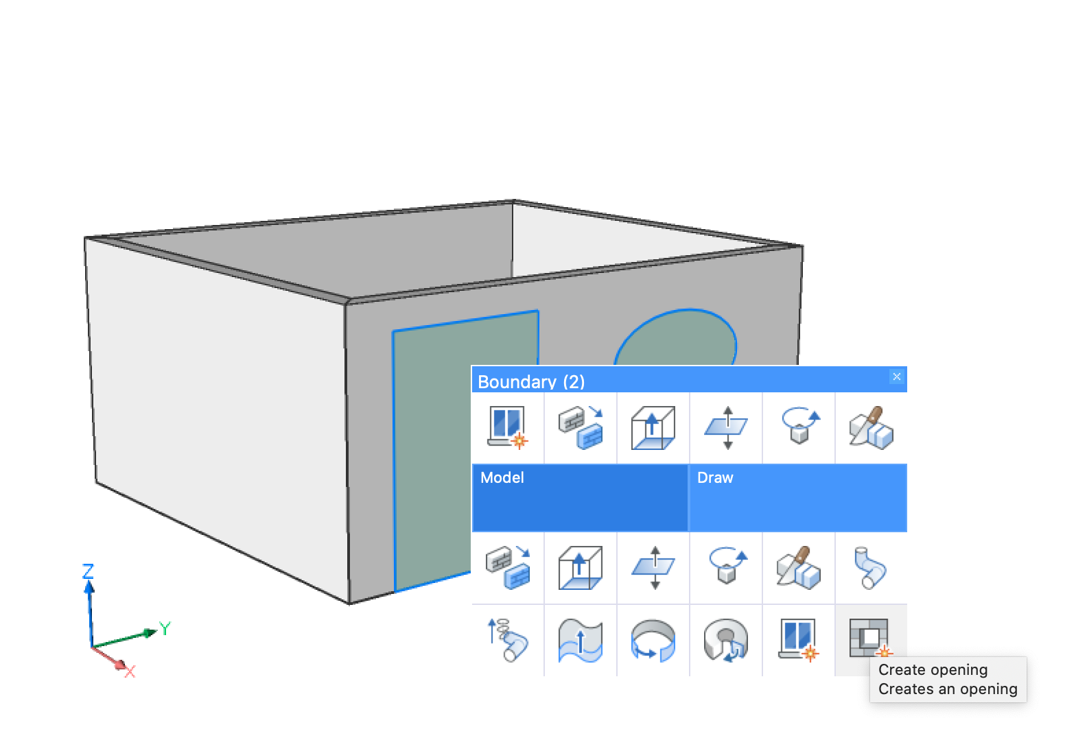
Select the Create Opening tool from the Quad.
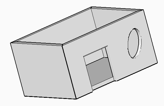
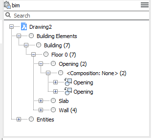
The opening is created based on the closed contour. In the
Structure Browser, the opening is added as a
block reference. The block reference is classified as an opening.
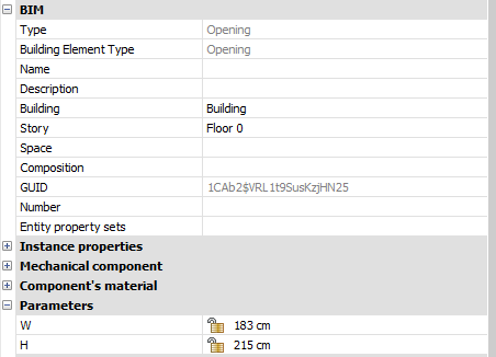
If you select the opening from the structure browser, you
will see a set of properties related to this opening element
in the Properties panel.
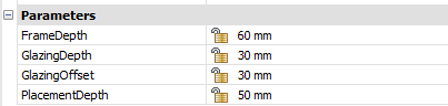
Note: If your closed contour has a
rectangle shape, the opening element will include
Width and Height parameters.
Note: Opening elements contain
subtractor solids. To display the subtractor solid,
open the Layers panel and
select the BIM_Subtract
layer.
Note: The associative tags can be
generated using the BIMTAG command for the opening
element in a sectioned drawing.
The following animated gif demonstrates how to create an opening based on a closed
contour.

 Note: You can edit the parameters in the Properties panel. Type a new value in the property field and press Enter. The window will automatically update itself.