Analyzing TIN Surfaces
Commands
TINVOLUME, TINWATERDROP
Overview
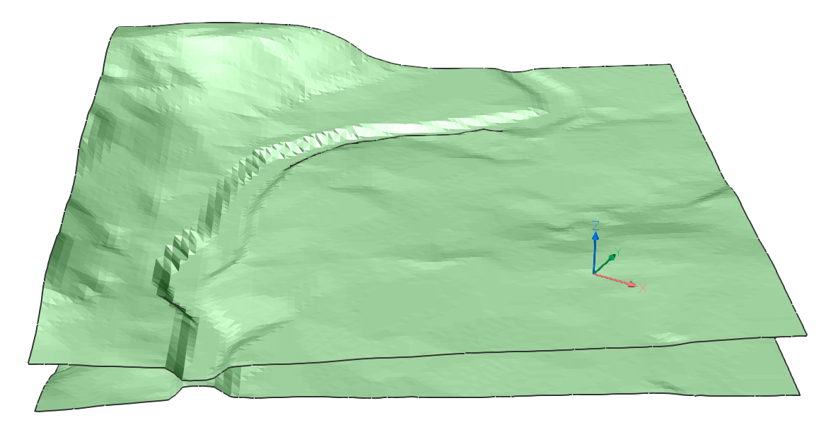
In BricsCAD, topographical surfaces created as a TIN Surface, can be analyzed using different tools.
About TIN Volume
A TIN volume surface provides an exact difference between the base and comparison surfaces. Therefore, the Z-value of any point in the volume surface is precisely the difference between the Z of the comparison surface at that point and the base surface at that point. A TIN Volume Surface is drawn as a custom entity with additional fill/cut volume properties.
You can use TIN Volume to calculate or analyze earthworks:
- Calculate fill/cut volumes inside bounding area.
- Draw zero contours which divide fill and cut areas.
- Visualize the mass distribution.
Procedure: Creating a TIN Volume
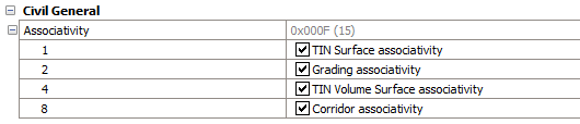
In the following procedures, a TIN Volume is created. Choose whether the volume is associative or not. If associativity is turned on: TIN Volume Surface is automatically updated if base or comparison surfaces are changed. To disable or enable the associativity, follow these steps:
- Type Settings in the Command line and press Enter.
- Go to .
- Check or uncheck TIN Volume Surface Associativity.
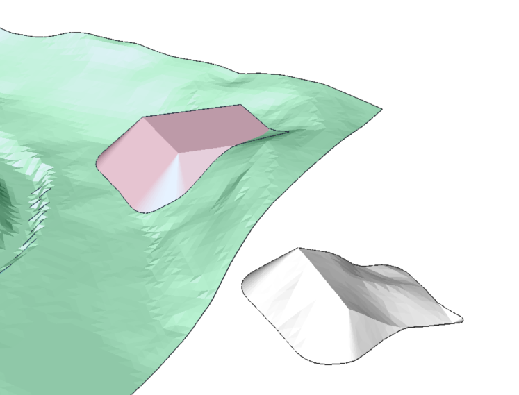
Creating a TIN Volume using a comparison TIN Surface
- Launch the TINVOLUME command.
- Choose a base surface. In this example, we choose the green TIN surface as the
base surface.
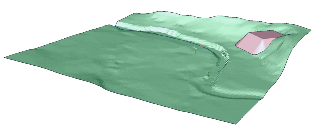
- Choose a comparison surface. In this example, we choose the red grading as the comparison surface.
- Select a bounding area as the area to apply the operation orpress ENTER. The outer boundary of the surface will be used as a boundary.
- The TIN Volume appears under the TIN Surface.
Creating a TIN Volume using Elevation
- Launch the TINVOLUME command.
- Choose a base surface.
- Select Elevation in the Command line.
- Choose the elevation height.
- Select a bounding area as the area to apply the operation or press ENTER. The
outer boundary of the surface will be used as a boundary.
About TIN Water Drop
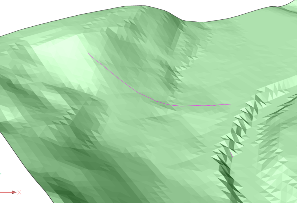
The TINWATERDROP command creates water drop paths in real-time by moving the cursor over a TIN Surface. Water path is created as a 3D polyline in the current position if you click the mouse button.
Procedure: Creating a water drop path
- Launch the TINWATERDROP command.
- Select the TIN surface.
-
Move the cursor over the surface, a line representing the drop path is shown in real-time.
Note: It would be better if the water drop path is colored so it could be seen clearer. To do so, you should change the current layer to another color, e.g. red.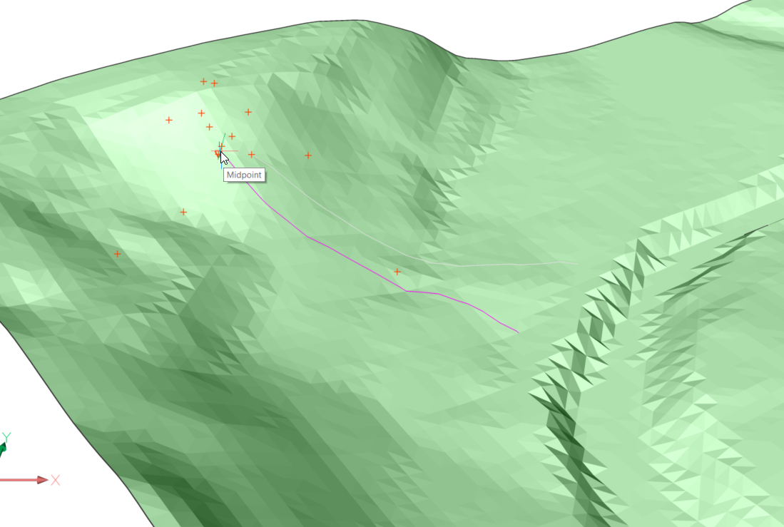
- Left click with the mouse to create a 3D polyline of the water drop path.