VIEWBREAK command
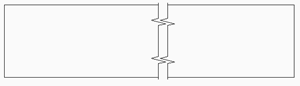
Creates a broken view on drawing views generated by the VIEWBASE command in a paper space layout.

Icon: 
Note: This command operates only in Paper Space.
Note: This command can be entered transparently during
commands (‘viewbreak)
Method
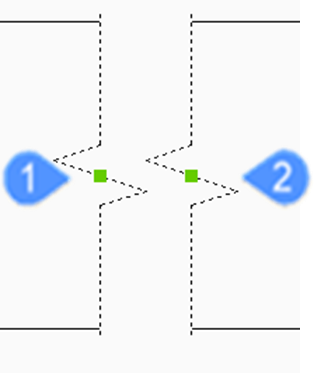
Select the drawing view from which to generate the broken view by clicking inside the drawing view. Select the first and the second points which specifies the first and the second planes of the cuts.
The default direction of the symbol is based on the size of the viewport:
- Vertical if the viewport is wider than high.
- Horizontal if the viewport is higher than wide.
Options within the command
- Type
- Allows to set the broken symbol type:
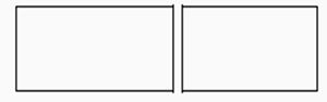
- sTraight
- Line geometry. Supports the Gap distance property.
-
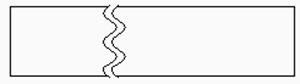
- Spline
- Spline geometry. Supports the Gap distance, Width and Height.
-
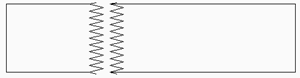
- Zigzag
- Spline geometry. Supports the Gap distance, Width and Height properties.
-
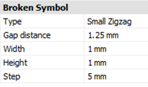
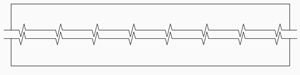
- sMall zigzag
- Supports the Gap distance, Width, Height and Step properties.
-
-
- Vertical
- Aligns the symbol along the Y axis.
-
- Horizontal
- Aligns the symbol along the X axis.
-
- Edit Grips
- You can edit break symbol grips.
-