BIM ply editing
Commands
LEVELOFDETAIL, RENDERCOMPOSITIONMATERIAL, DMPUSHPULL
About
The BIM Ply Editing function allows you to manipulate all the composition plies in your model. In BricsCAD, each drawing has settings stored inside to control the composition plies, called LOD (LEVELOFDETAIL), and the render materials, called RENDERCOMPOSITIONMATERIAL. These two settings can be turned on/off separately.
Composition plies and render materials
Composition plies display only when LEVELOFDETAIL = 2 (high).
Building elements do not need to be selected, they will be automatically adjusted. When LEVELOFDETAIL = 0 (low) the material definition of the solid is used.

For more information about this setting visit the article LEVELOFDETAIL.
Render materials display only when RENDERCOMPOSITIONMATERIAL = 1 (on). The render material of each ply is defined in the 3D Render Material setting of the material definition.

RENDERCOMPOSITIONMATERIAL = 1 (on)
- LOD =0, RENDERCOMPOSITIONMATERIAL = 0
The material definition of the solid is used and no materials are displayed.
- LOD =2, RENDERCOMPOSITIONMATERIAL = 0
The solid is subdivided into plies, no materials are displayed. When face detection is turned on, you can select the faces of different plies to push/pull for example.
- LOD =0, RENDERCOMPOSITIONMATERIAL = 1
The material definition of a solid is used. The materials of the exterior and interior face are displayed and the material of the exterior layer will be wrapped around the object.
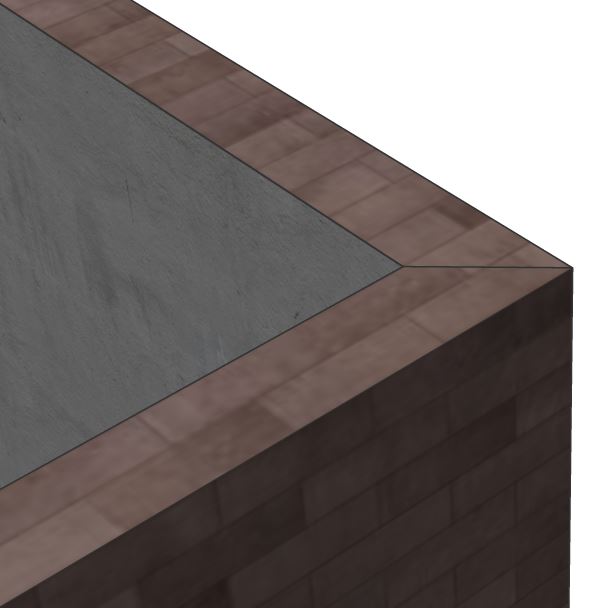
- LOD =2, RENDERCOMPOSITIONMATERIAL = 1
The solid is subdivided into plies. Each ply will be displayed with its own material. When face detection is turned on, you can select the faces of different plies to push/pull for example.
Manipulating the composition plies
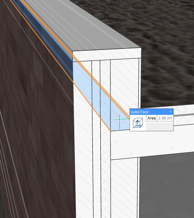
- Make sure the value of LEVELOFDETAIL = 2 (High).
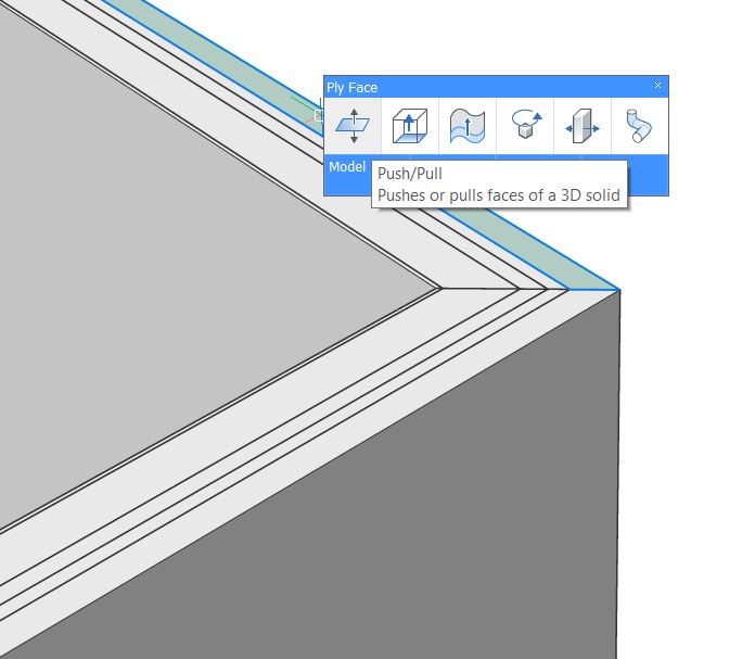
- Place your cursor near the composition ply you want to edit and press the
Tab key until the Ply face (1) highlights.
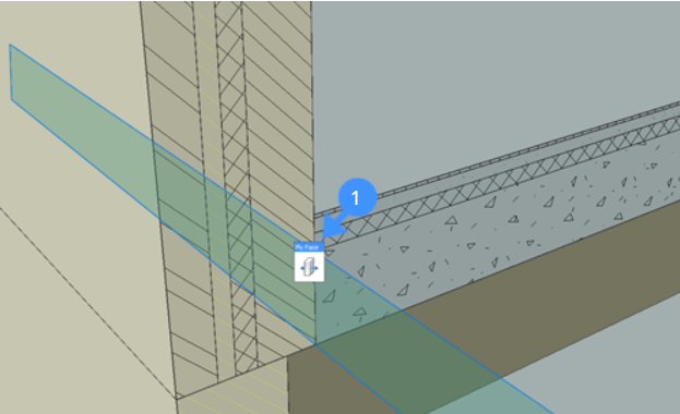
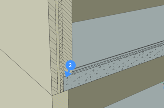
Note: The highlighted ply face is displayed in the detected boundary color (default = 95). Face detection must be enabled to do this. - Select Push/Pull from the Quad and drag the ply to a
new position (2).
Procedure: creating a rooftop detail
It is also possible to create more complex details with extra solids added apart from the existing compositions. As an example, a rooftop detail will be created, starting from a rooftop edge.
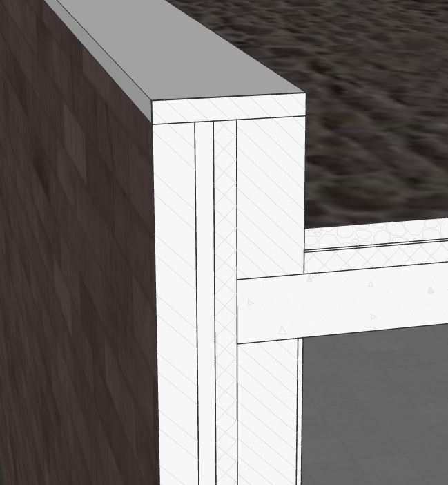
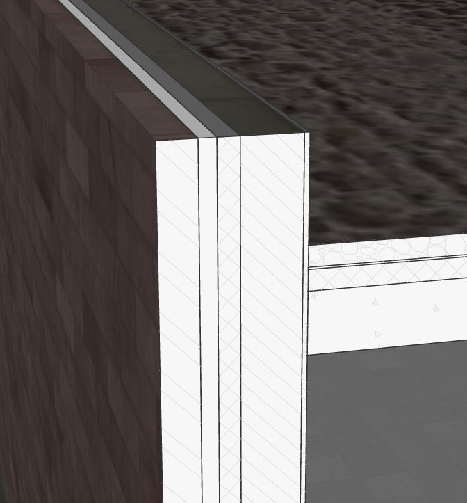
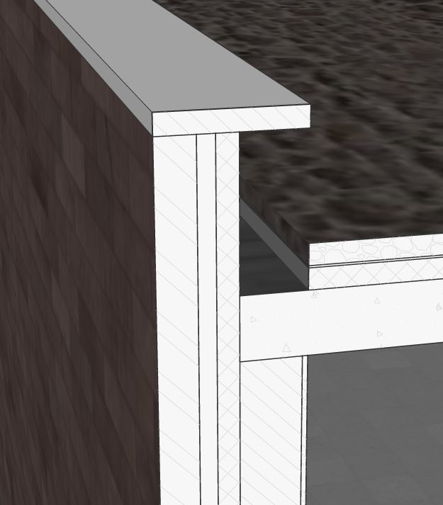
- tart with this roof-wall connection.
- Click the Face detection icon in the ribbon to enable face detection.
- Turn on LOD to be able to select ply faces. Click the icon in the ribbon or type LEVELOFDETAIL in the Command line, type 2 and press Enter.
- Hover over the edge of the concrete ply of the floor slab and press Tab to select the face of the ply.
- Choose Push/Pull in the model
tab of the Quad.
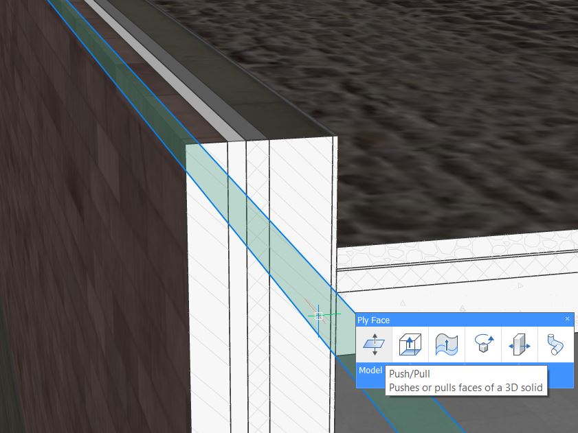
- Push/Pull the face to the next ply of the wall.
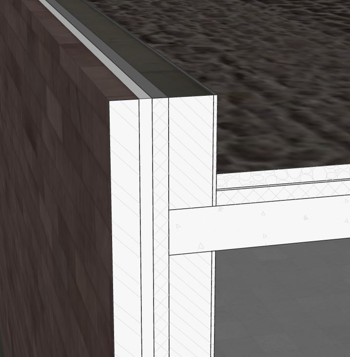
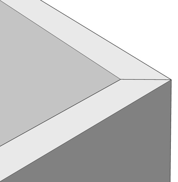
- To create a wall cap, select the top surface of the wall by pressing Tab and
extrude the surface up for 50mm. The created cap isn't classified yet.
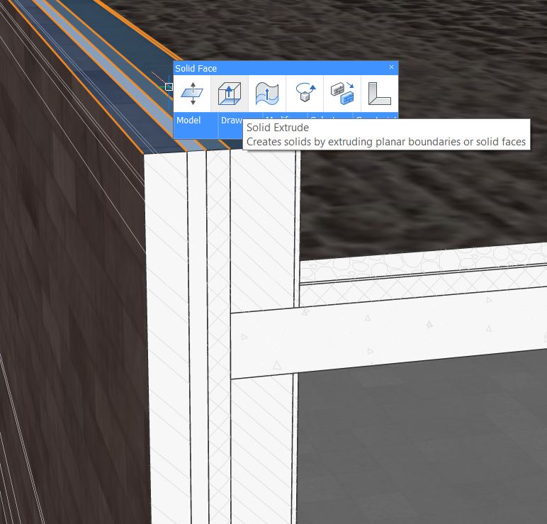
- Delete the part where the insulating building block will come. Hover over
the surface of the supporting wall and the gypsum board and press tab to
select the surface. Then Extrude till the ply of the wall cap.
- Extrude the same surface again, now a new solid will be created.