Working with Hole Features
Overview
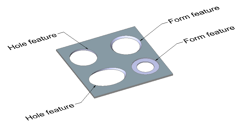
Hole features are a simplified version of Form Features. In the image
below you can see different features, which have only thickness faces (the
SMCONVERT command respects these rules):
- Orthogonal holes are hole features.
- Simple non-orthogonal holes are hole features.
- Chamfered orthogonal holes are form features.
- If the hole thickness face consists of 2 different regions, it is a form feature.
Hole features are recognized by the SMCONVERT command if the SMCONVERTRECOGNIZEHOLES user preference is ON.
The following basic operations are allowed for hole features:
- SMDELETE, SMDISSOLVE, disable and SMSELECT them using commands or in the Mechanical Browser for Sheet Metal.
- Form Feature Modes in the SMUNFOLD command, including Symbol mode.
- Associate your own 2D geometry in a flattened layout.
- Hole features are preserved by the SMREPAIR command. Plain hole faces become orthogonal. A hole feature of the same geometry is not affected by the SMREPAIR command.
Recognition of Arrays of Hole Features
When hole features exist in a body, the SMPARAMETRIZE command
detects rectangular arrays of holes on flanges, according to the following rules:
- Holes belong to the same flange.
- Holes are on a rectangular grid.
- There are no gaps (missing elements) in the array.
- Holes are equally oriented.
- The minimal array size is either 1x3 or 2x2.
Let us illustrate the workflow on a part with Flange and Bend features.
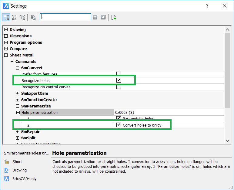
- In the Settings dialog box, go to Sheet Metal/Commands.
- Enable the Recognize holes option for the SMCONVERT command.
- Enable the Convert holes to array and
Parametrize holes options for the
SMPARAMETRIZE command.
- Run the SMCONVERT command.
- Do one of the following:
- Click the Convert to Sheet Metal tool button
(
 ) on the Sheet Metal
toolbar.
) on the Sheet Metal
toolbar. - Click the Convert to Sheet Metal tool button
() on the Sheet Metal
ribbon bar.
- Choose Convert to Sheet Metal in the
Sheet Metal menu.You are prompted: Select 3D solids or [Entire model] <Entire model>:
- Click the Convert to Sheet Metal tool button
(
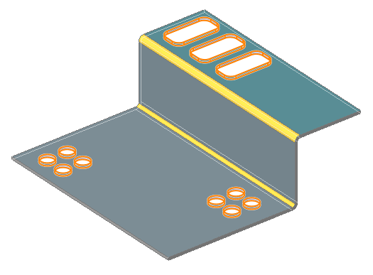
- Select the 3D solid to convert.You are prompted: Select 3D solids or [Entire model] <Entire model>:
- Press Enter to convert the 3D solid to sheet metal
part.11 hole features are recognized on the part.
- Run the SMPARAMETRIZE command.
- Do one of the following:
- Click the Parametrize tool button (
 ) on the Sheet Metal
toolbar.
) on the Sheet Metal
toolbar. - Click the Parametrize tool button () on the Sheet Metal
ribbon bar.
- Choose Parametrize in the Sheet
Metal menu.You are prompted: Select 3D solids to parametrize or [Entire model] <Entire model>:
- Click the Parametrize tool button (
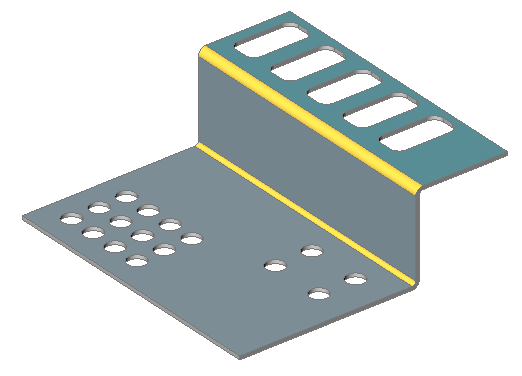
- Press Enter to process the sheet metal part.The command reports must look like the one below:Created 4 distance constraintsCreated 3 fix constraintsCreated 0 coincident constraintsCreated 0 tangent constraintsCreated 0 rigid set constraintsCreated rectangular array 2x2 basing on Hole_3 featureCreated rectangular array 2x2 basing on Hole_7 featureCreated rectangular array 3x1 basing on Hole_9 featureTotal: 7 constraints and 3 array(s) createdNote: Feature names and constraint distribution may differ depending on the BricsCAD version.To examine the arrays, you can temporarily unfreeze the BC_SUBTRACT layer.In the image below the arrays are colored manually.
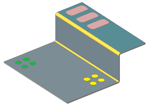 Note: The green and yellow arrays are not unified. Otherwise the array would have missing holes.
 - Edit the Array Properties in the Mechanical
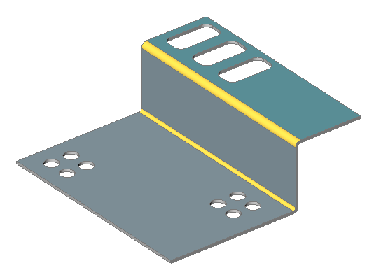
Browser.In the image below the following has been modified:
- Green array: number of rows and columns from 2x2 to 3x4.
- Yellow array: X and Y spacing.
- Red array: number of rows and columns from 3x1 to 5x1.