The new MOVEGUIDED command enables you to move selected entities using reference
curves.
When you launch the MOVEGUIDED command and select the entities you want to move,
entities that fall completely within the selection window will be moved. Entities
crossing the selection window are used as reference curves. Blue vectors on
the selected entities represent the reference curves. As you move the selected entities
near geometry that matches the reference curves, they automatically snap into place.
Relevant geometry in the new location is automatically trimmed and geometry in the
original location is automatically healed. This significantly reduces the amount of
manual editing required!
For more flexibility, you can first select the entities you want to move and then launch
the MOVEGUIDED command. The pre-selected entities are used for the Move selection set
and you are prompted to select entities to use as reference curves.
Copy in a linear array
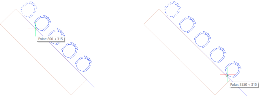
The COPY command now includes a new Array option enabling you to
copy selected entities in a linear array. The new Array option is available after you
specify the base point for the copy operation.
You specify the number of copies to array then pick a point to specify the distance and angle between the first two sets of entities or use the Fit option to specify the distance and angle between the first and last sets of entities.
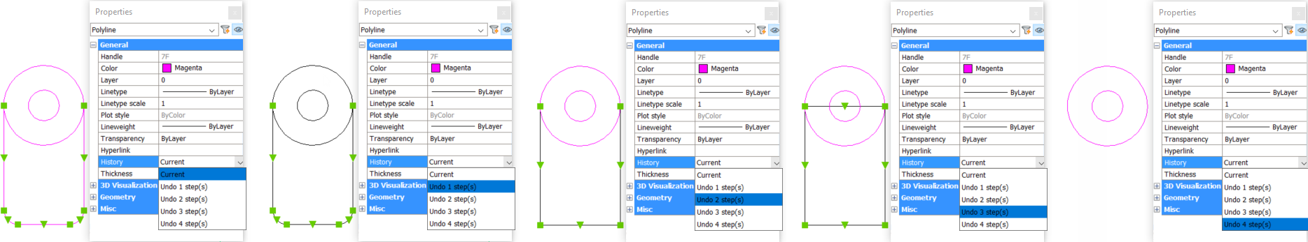
Undo per entity
A new History control in the Properties panel enables you to undo editing operations for
a selected entity. The History property only displays when you select a single entity.
Open the History drop-down list to undo the entity back to one of the previous steps
without undoing all the other commands and view operations that have been executed
since.
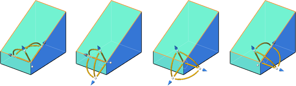
Manipulator
Press the SHIFT key to rotate the Manipulator 90 degrees about its normal axis.
The Copy and Repeat options in the Manipulator are now visible, clickable, and localized.
Nearest Distance
The NEARESTDISTANCE system variable offers improved performance and behavior including
support for Point entities.
Layers
BricsCAD® V21 offers several layer
enhancements to help increase your productivity.
Layer Translator
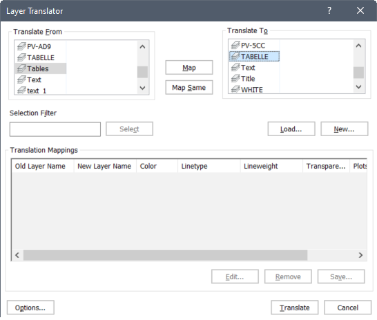
The new LAYTRANS command enables you quickly apply layer names and properties from
another drawing file to the current drawing. When you launch the LAYTRANS command, the
Layer Translator dialog displays. All the layer names in the current drawing are
displayed in the Translate From list. You can specify the layers to which you want them
to map by loading layer information from an existing DWG, DWS, or DWT file.
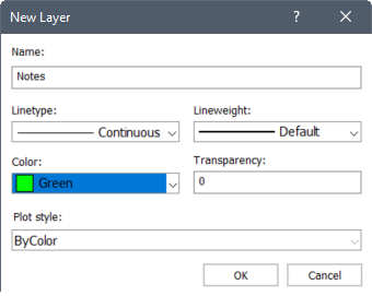
You can also create new layers. Simply enter the layer name and properties to which you want to map existing layer.
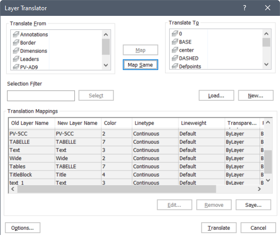
You can select one or more layers from the current drawing, the list on the left, to map to a layer from the list on the right. If you choose Map Same, any layer names in the current drawing with corresponding names in the list on the right will inherit the properties from the list on the right. The layer mappings you select are displayed in the Translation Mappings list.
Regardless of how you add layers to the Translation Mappings list, you can modify their mapping properties. Double-click on a layer or choose Edit to open the Edit Layer dialog box with the same options at the New Layer dialog. You can also remove layers from the Translation Mappings list or save the mapping list to use again in the future.
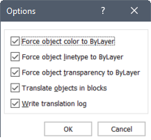
The Options dialog offers additional controls for layer mappings.
Set by Layer
The new SETBYLAYER and -SETBYLAYER commands enable you quickly change property overrides
of selected entities to ByLayer.
Use the new SETBYLAYERMODE system variable to control which properties are affected by
the SETBYLAYER commands. The value is stored as a bitcode using the sum of the values of
all selected options.
1: Color
2: Linetype
4: Lineweight
8: Material
16: Plot style
32: ByBlock
64: Blocks
128: Transparency
Layer properties by Viewport
The VPLAYER command is enhanced in 21 allowing you to select entities on layers for
which you want to apply viewport overrides. After selecting which layer property you
want to modify for the viewport, you can type the name of the layer or press enter to
specify the layer by selecting an entity on that layer.
Linetypes
BricsCAD® now supports selection of
linetype gaps with the addition of the LTGAPSELECTION system variable. With
LTGAPSELECTION enabled, entities are highlighted and selected even when you pick in the
gap.
Parameters & Constraints
BricsCAD® V21 offers powerful enhancements
for creating parametric drawings and block definitions.
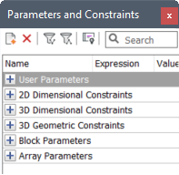
Parameters & constraints panel
All BricsCAD® license levels now support 2D
parameters and constraints. View and modify parameters and constraints in the Parameters
and constraints panel. The panel is extended to display 3D geometric constraints, 2D
dimensional constraints, parametric blocks, and arrays.
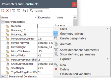
The right-click menu for parameters and constraints enables you to specify if parameters
are geometry-driven. Expressions for such parameters cannot be edited (you can switch
geometry-driven status off to edit them) – instead they are automatically computed from
3D geometry via 3D dimensional constraints that depend, directly or indirectly, on
geometry-driven parameters. Simple arithmetic expressions for such 3D dimensional
constraints are solved in dynamics when you change your geometry with direct editing
tools such as DMPUSHPULL or DMMOVE/DMROTATE.
The right-click menu also enables you to control if a parameter is exposed for editing when inserted as a block.
If you open a 3D parametric model with a BricsCAD® Lite license, 3D constraints are shown
in magenta. You can view and edit their expressions with BricsCAD® Lite. However, the 3D model only
reflects the changes after it’s opened with a BricsCAD® Pro license or above.
Automatic constrain
The new AUTOCONSTRAIN command enables you to automatically apply 2D geometric and
dimensional constraints to selected 2D geometry. BricsCAD® fully constraints the geometry,
ensuring not to over-constrain it. The geometric and dimensional constraints are
displayed on the geometry. You can view, add, remove, and modify the parameters and
constraints in the Parameters and Constraints panel.
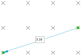
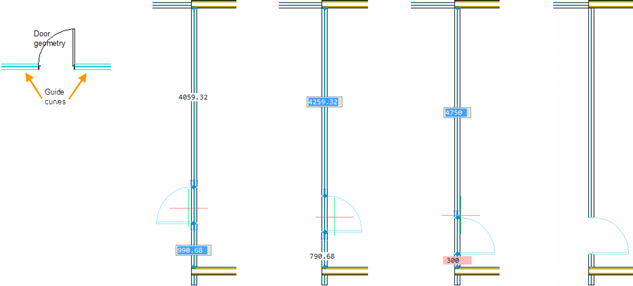
Reference curves
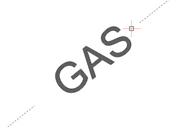
The new REFERENCECURVES command enables you to specify reference geometry for blocks.
When you select geometry to use for reference, BricsCAD® creates a REFERENCE_CURVES layer
(if it doesn’t already exist) and adds the selected entities to that layer.
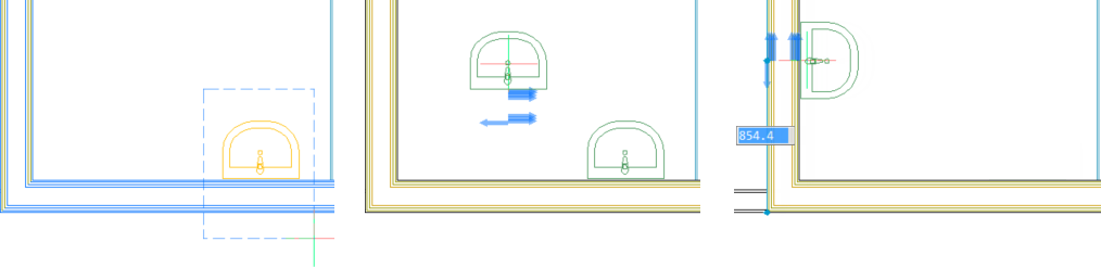
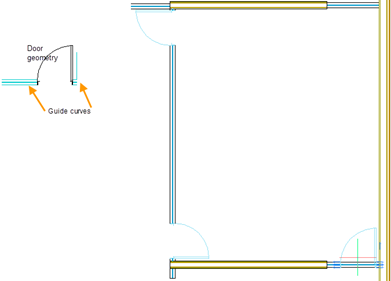
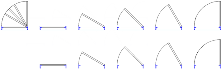
With reference curves specified in a drawing or block definition, you can automatically align the block or drawing to relevant geometry when you insert it. The number of reference curves and the distance between them determines with which geometry it can align. As the cursor approaches relevant geometry, the block can automatically flip, offering multiple insertion options. Distances between the ends of the relevant geometry and block are displayed, enabling you to enter specific values if you wish. And, if the reference curves include gaps, relevant geometry is automatically trimmed to produce matching gaps.
You can also use reference curves to automatically align with corners. The following example includes 4 parallel reference curves and a single corner reference curve enabling the door block to align with geometry that matches the four parallel lines and single perpendicular line.
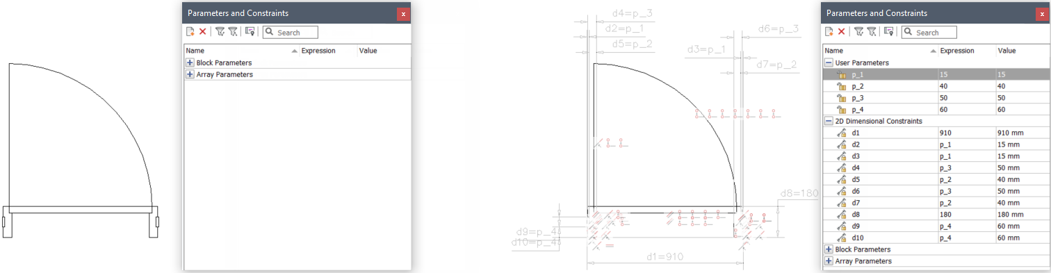
Visibility states
The new VISIBILITYSTATES command enables you to define visibility parameters and states.
You can create multiple visibility parameters in a drawing or block definition. And, you
can create multiple visibility states in each visibility parameter. When you insert the
drawing or block, you can change the visibility of each instance. For example, you might
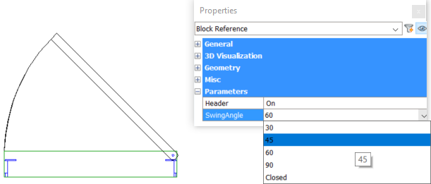
create a door block with two visibility parameters, SwingAngle and Header.
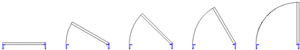
The SwingAngle parameter includes 5 visibility states: Closed, 30, 45, 60, and 90.
The Header parameter includes two visibility states: On and Off.
You create all the geometry for each of the visibility states and then select the appropriate geometry to display in each state of each parameter. Geometry that doesn’t belong to a visibility state is always displayed. This door example enables 10 variations of block insertions.
You can easily change the visibility states for a selected block insertion using the Properties panel.
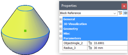
3D Radius constraints
The DMRADIUS3D command enables you to create geometry-driven 3D radius constraints to
measure the radius of entities inside blocks.
Blocks
BricsCAD® V21 offers many enhancements to
increase your productivity when working with blocks.
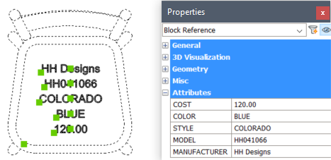
Block attribute properties
You can now access block attribute properties in the Properties panel. This allows you to view and edit multiple attributes at the same time. Press the Ctrl key to select one or more attributes within block instances. Open the Properties panel to display the Attributes entity type with all the relevant attribute properties.
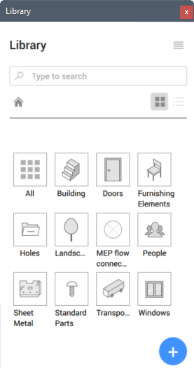
Library panel
The new Library panel offers a central location to access 2D and 3D block libraries. It replaces both the Components and the 2D Parametric Blocks panels from previous releases.
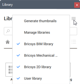
A menu in the upper right corner allows you to control which content is displayed in the Library panel. It may include pre-defined content from Bricsys libraries as well as the User Defined library with your own content.
You can specify where BricsCAD® looks for
library content by selecting the Manage libraries option. It offers quick access to the
COMPONENTSPATH setting so you can view and modify library folder locations. Another menu
option automatically generates thumbnail images for any that are missing.
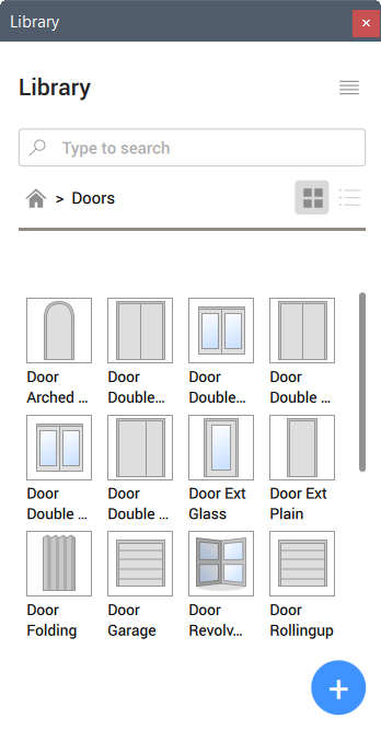
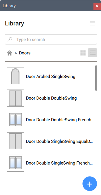
You can search for content by typing key words in the Search box or expand a category to
see all the content within that category. And you can display the content in a grid or
list view.
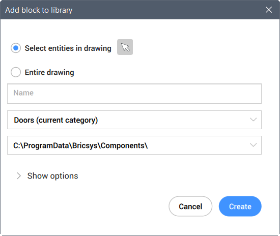
You can easily add new block definitions to the library using the Add button at the bottom of the Library panel. Select specific entities from the drawing or use the entire drawing.
Block icons
The new BLOCKICON command creates or updates thumbnail images that enable you to preview
blocks with various tools including Drawing Explorer and the Library panel.
Non-uniformly scaled blocks
The EXPLODE command and the XPLODE command now honor the EXPLMODE system variable when
exploding non-uniformly scaled blocks.
Insert
The INSERT command is enhanced to support parametric blocks. Block definitions
containing parametric entities with exposed parameters can now be parametrically changed
after insertion by the INSERT Command. To insert parametric BIM and Mechanical
components, use the BMINSERT command.
Drawing Optimizations
A new Drawing optimizations ribbon panel offers tools to clean up and optimize your
drawings.
Simplify
The new SIMPLIFY command reduces the number of vertices of polylines and hatch
boundaries without changing their general shape. Options allow you to switch between
simplifying and smoothening. Additional options enable you to control the amount of
deviation from the original entity. Simplified entities are easier to manipulate and can
significantly reduce file size.
Purge
The PURGE command is enhanced so the Batch, All, and Orphaned data options remove more
items from the drawing.
Audit
The AUDIT command is enhanced to clean up duplicate ACIS attributes. A combination of
AUDIT and CLEANUNUSEDVARIABLES now cleans a drawing from multiple orphan parameters.
Delete Duplicate Entities
The OVERKILL command enables you to choose if you want to delete duplicate entities or
move them to a specified layer. You can specify the layer name using the new
OVERKILLLAYER setting or leave the default name, Duplicate Entities.
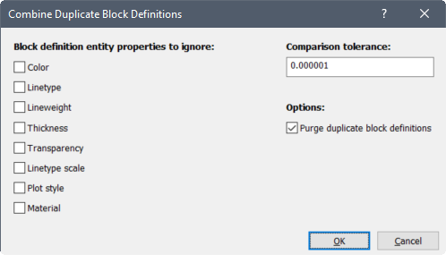
A new option in the OVERKILL command allows you to combine duplicate block definitions.
Choosing this option displays the Combine duplicate blocks dialog box where you can
specify any block properties you want to ignore. You can specify how closely the
geometry must match by entering a comparison tolerance. If BricsCAD® finds more than one block
definition whose geometry meets the tolerance and properties criteria, it uses the most
recent definition to replace any instances of the older definitions. The older
definitions become unused and you can enable the Purge duplicate blocks option to
automatically purge them.
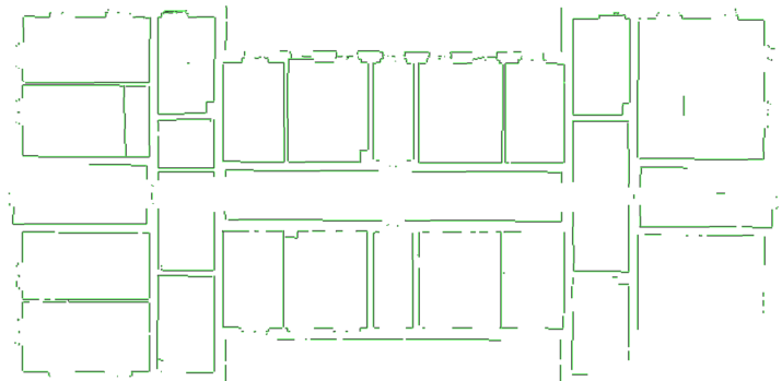
Optimize
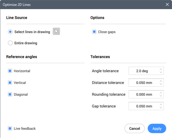
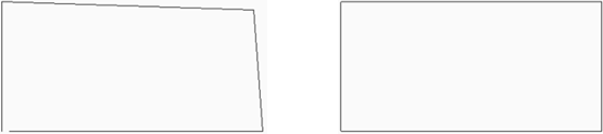
The new OPTIMIZE command helps you clean up 2D lines in your drawings. It displays the
Optimize 2D Lines dialog box where you can control which lines are affected. Specify
which lines BricsCAD® should consider for
optimization. You can select specific line entities or have BricsCAD® analyze and optimize all line
entities in the drawing. It can find and fix lines that are within a specified angle
tolerance relative to horizontal, vertical, or 45 degrees, in the current UCS. An
additional option automatically closes gaps within a specified tolerance.
The Optimize tool is useful for cleaning up any 2D lines. For example, you can use it to quickly clean up line geometry extracted from point clouds.
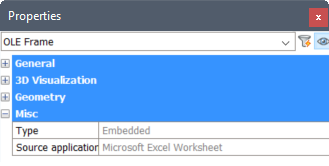
Object linking and embedding
The Properties panel for OLE objects is enhanced to provide additional information for
the selected OLE entity. The additional information may include Type, such as Embedded
or Static, Plot quality, and Source application.
Images
Image manipulation is enhanced in BricsCAD®
V21. When you manipulate an attached image using grips and other editing tools the image
content displays and updates as you edit the image frame. This enables you to position,
align, and scale the image using the image content for reference. The selected image
temporarily displays above any overlapping objects as you edit it.
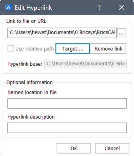
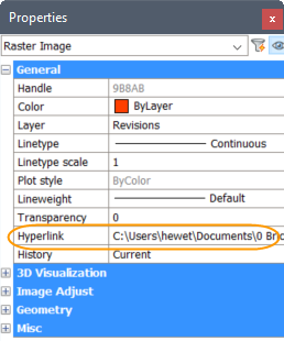
Hyperlinks
The Edit hyperlink dialog box now enables you to link to layouts and views inside a
drawing. After selecting the drawing to which you want to link, choose
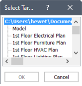
Target to open the Select Target View dialog box.
The Select target view dialog box displays a list of all named views and layouts in the
linked drawing.
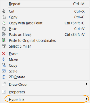
To access a hyperlink, double-click on the hyperlink in the Properties panel for the selected entity or press and hold the right mouse button and choose Hyperlink from the menu.