Point cloud functionality is even more powerful with a BIM license.
Floor Detection
Sectionplanes work on point clouds as well, they can be used to show parts of point clouds. The difference between point cloud crops and sectionplanes is that point cloud crop only clips the point cloud while section planes will clip all geometry in your drawing.
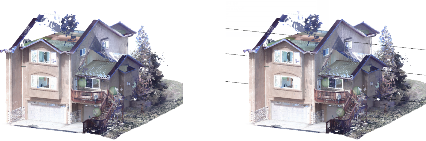
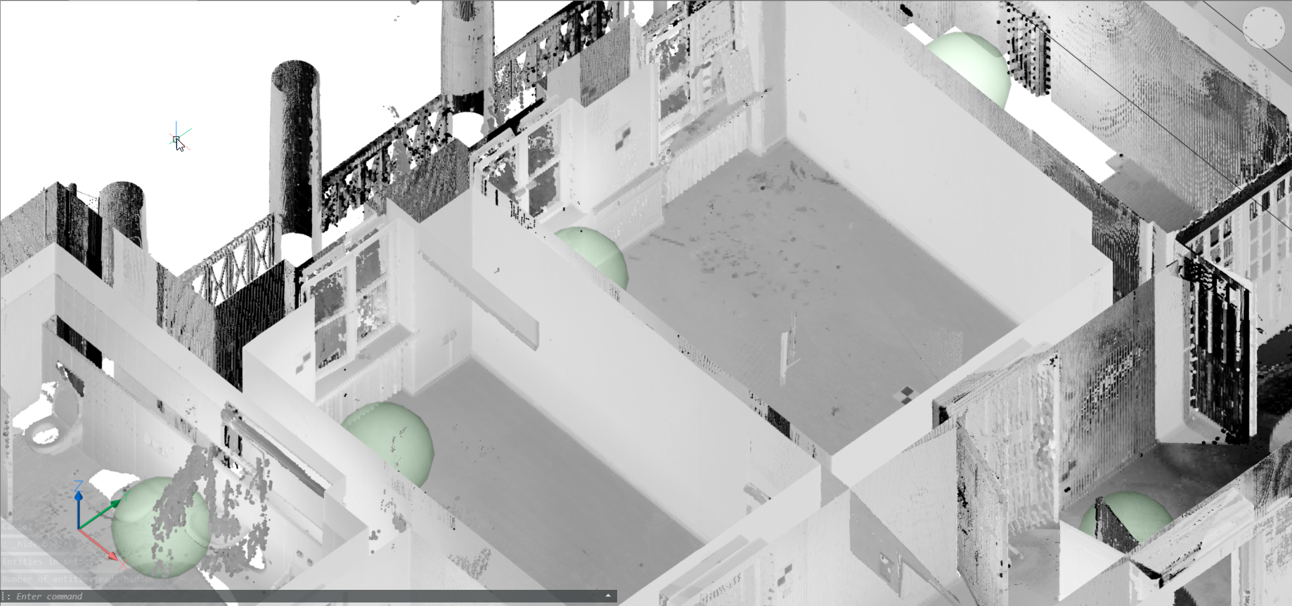
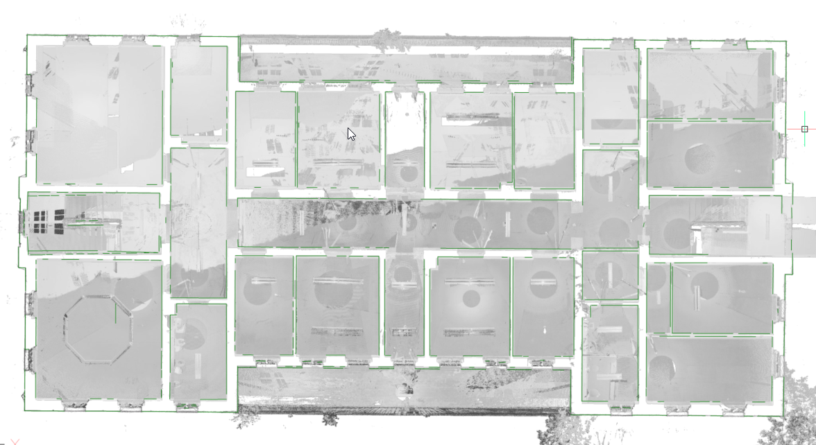
The new POINTCLOUDDETECTFLOORS command generates volume sections for each floor found in
a point cloud representing a building. The detection is based on regions of points with
similar Z-coordinates. The generated volume sections can help in navigating point clouds
of buildings.
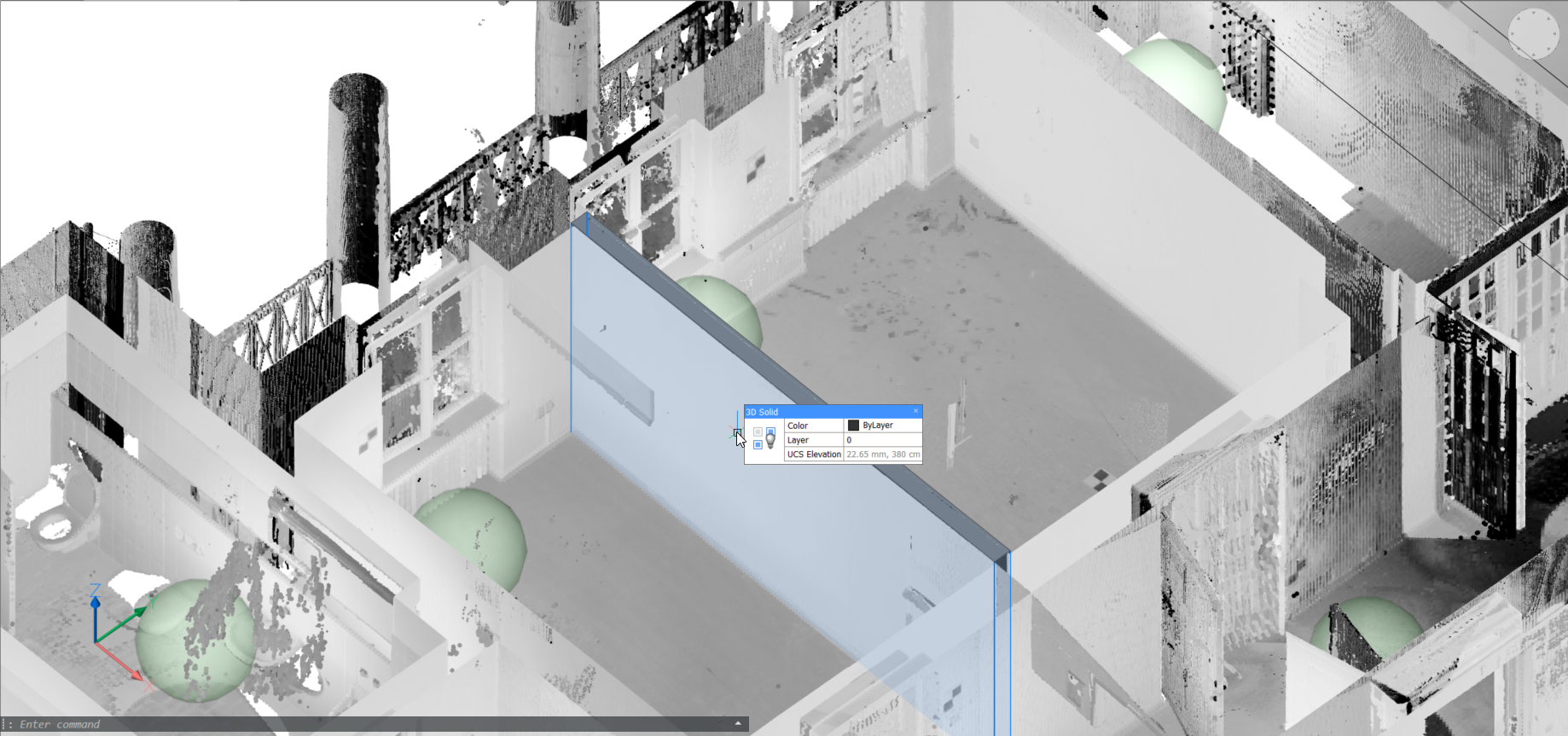
Planar Fit
The new POINTCLOUDFITPLANAR command enables you to create 3d geometry based on the point
cloud. It will create a planar surface or solid after a selection of one point in a
point cloud. The points that seem to be in a plane are never exactly in one plane,
therefore a threshold value is set as a property of the point cloud entity. This also
works in bubble view.
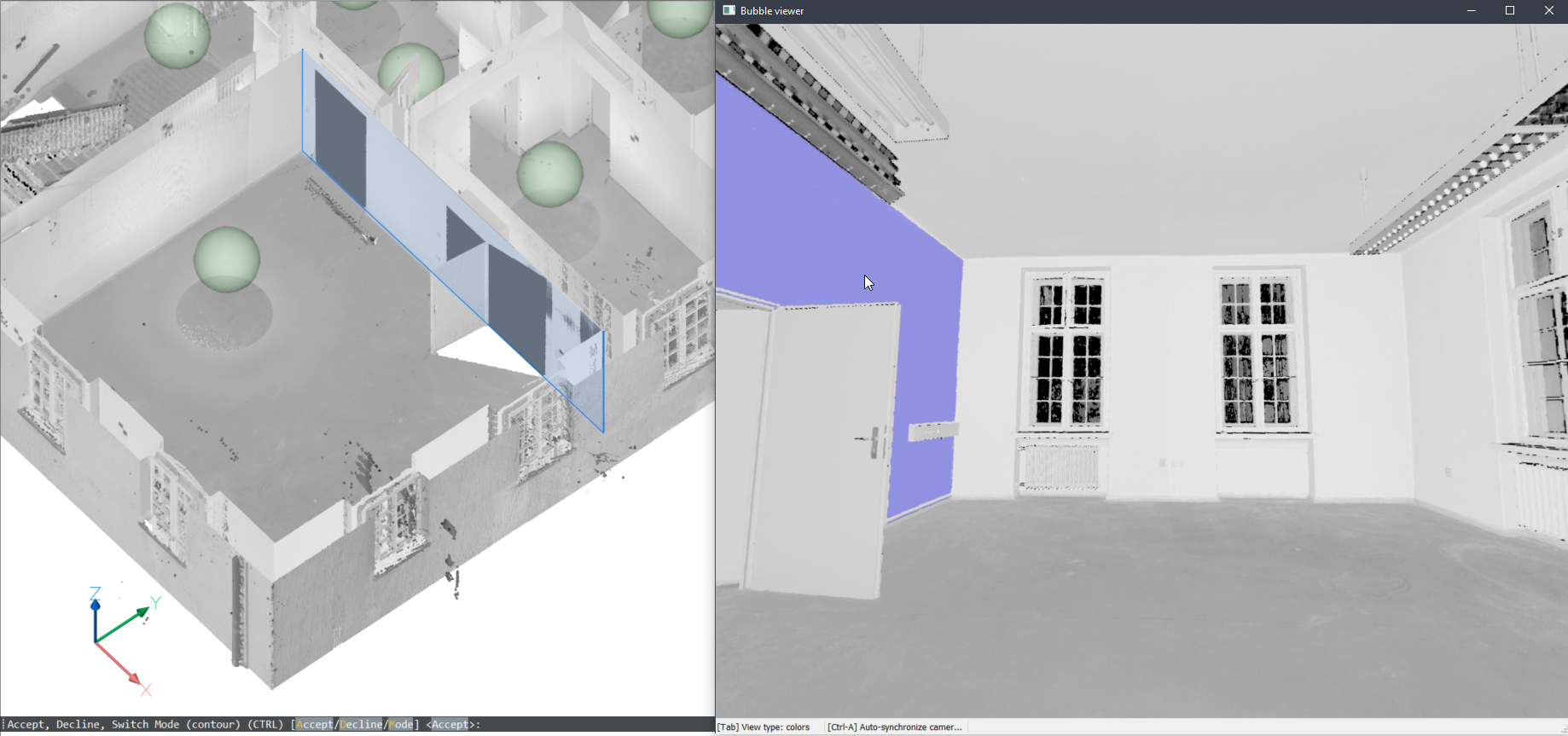
In bubble view
If the bubble viewer is open before launching the command, BricsCAD expects you to select in the bubble viewer. The cursor will give you a preview of the direction of the plane. When you click you get a preview in both bubble view and model view. You can toggle between 2 shape representations using the CTRL key.
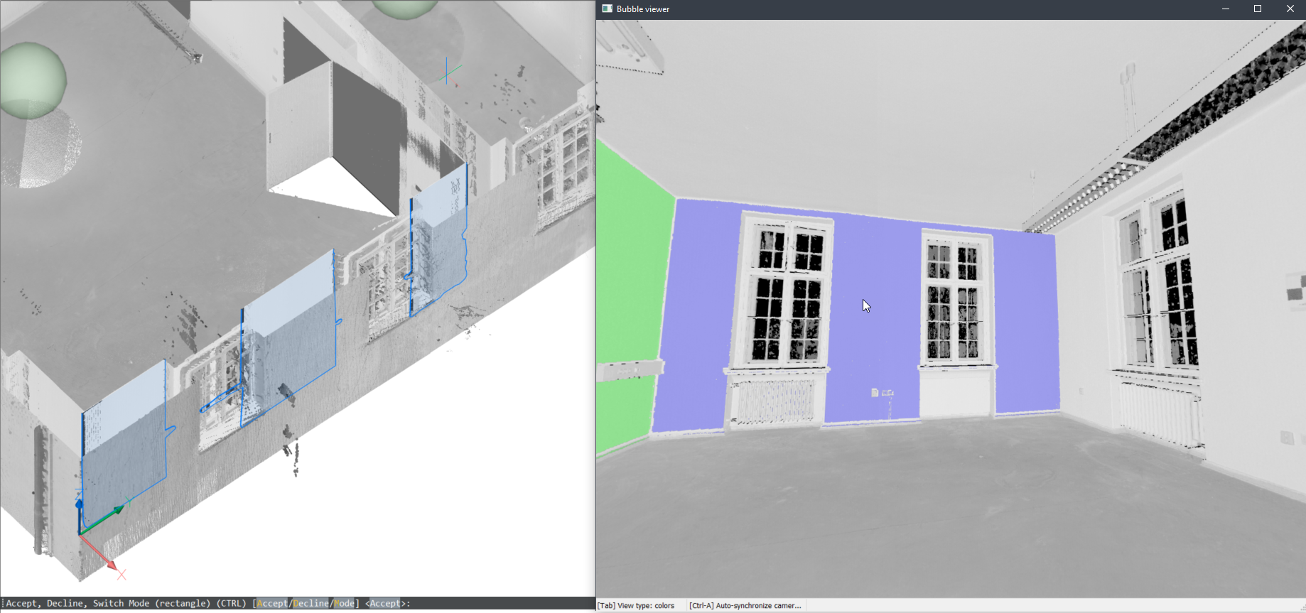
In model space
You can also use this command in the model space when the bubble viewer is not open. BricsCAD will ask you to select a point of the point cloud in model space. Depending on the size of the cropped point cloud, it takes more time but it has 2 advantages by searching multiple scan positions:
It can create larger surfaces where only parts are visible in each scan position
It can detect wall and slab thickness since it can take the opposite surface into account.
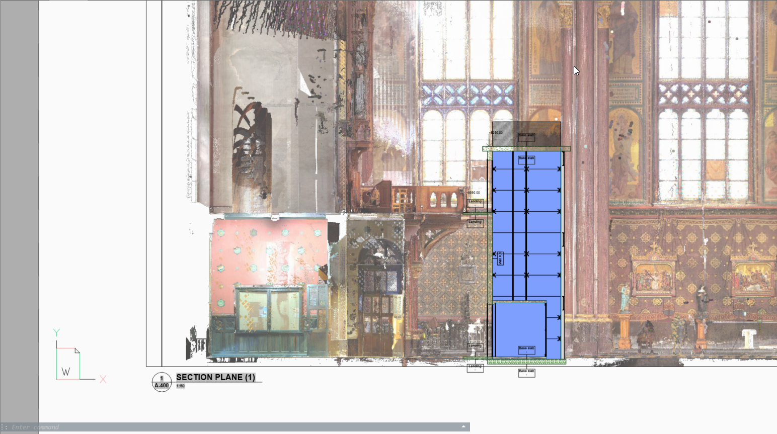
Point cloud projection
The new POINTCLOUDPROJECTSECTION command enables you to detect walls from the volume
section of a point cloud based on a variety of wall detection options. You can create
volume sections automatically for each floor in a building. You can use these sections
to generate 2d lines to create a 2d floorplan or a vertical section. This is a
background process and multiple sections can be processed in a queue. This way it is
possible to run this command in full resolution on all sections.
At the same time, a raster image will be generated. In some cases it is not necessary to recreate the existing building. Background images can give so much more context to the design documents. These can be used to verify the created 2d geometry but in high quality scans these images can also be used as graphical material. For example, as a background image for a BIM model in renovation projects where modern intervention are made in historical buildings.