Inserting and editing windows and doors
Commands
BIMINSERT
About

For more information about this command, visit the Command Reference article BIMINSERT.
Controlling the position of the window or door
- Dynamic Dimensions: During placement of a window or
door on a 3D Solid face, dynamic dimensions are created, starting from the
middle of each edge of the bounding rectangle of the opening to the nearest
parallel edge on the face of the 3D Solid. Make sure Dynamic
Dimensions are active by checking the DYN field in the
status bar and Dynamic UCS is active by checking the
DUCS field in the status bar.
The Dynamic UCS aligns the window to the face of the solid. The edge of the face by which the cursor enters the face defines the orientation of the X-axis. Hit the Shift key to temporarily lock the UCS, which allows to use reference points outside the face of the solid. Hit the shift key again to unlock.
- Temporary Tracking points: Click the mouse wheel or
press the Temporary Tracking Points tool button
(
 ) on the
Entity Snaps toolbar to start specifying
temporary points.
) on the
Entity Snaps toolbar to start specifying
temporary points. - OSNAPZ: If this system variable is ON, the Z-value of
any entity snapping point is replaced by the current value of the ELEVATION
system variable. If ELEVATION=0, entity snapping points are forced to lie in
the face of the solid. OSNAPZ is toggled by the Ignore entity snap elevation
tool button (
 ) on the
Entity Snaps toolbar. The state of the tool
button (pressed or not) indicates the current value of
OSNAPZ.
) on the
Entity Snaps toolbar. The state of the tool
button (pressed or not) indicates the current value of
OSNAPZ. - Entity snap to negative Z-values: Press the
Entity snap to negative-z tool button (
 ) on the
Entity Snaps toolbar to enable entity snaps on
points that lie behind the selected face. If OSNAPZ
is ON, the point is projected onto the selected face.
) on the
Entity Snaps toolbar to enable entity snaps on
points that lie behind the selected face. If OSNAPZ
is ON, the point is projected onto the selected face.
Procedure: inserting windows or doors
- Select Insert BIM Componentfrom the
Model tab of the No Selection Quad.
The file explorer opens, displaying the content of the most recently used folder to insert a BIM component. The default folders for BIM components sit in the following subfolder of the BricsCAD installation folder: ...\UserDataCache\Support\en_US\Bim\Components.
- Select the Windows (1) or
Doors folder.
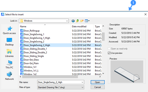
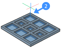
- Select a window or door you want to insert in your drawing, then double
click or click the Open button. The selected insert is attached to the cursor (2).
The parameters of the insert display in the Properties panel.
Prompts you: Select insertion point or [Edit inserted entity/Rotate component/set Base point/Name/insertion Type/Flip/mUltiple/Change target 3d solids] <0, 0, 0>:
- Optionally, edit the parameters in the Properties panel or choose an option (see Command Options of the BIMINSERT command).
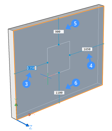
- When you move over a face of the solid, the insert aligns with the face
under the cursor. The distances from the start (3), end (4), top (5) and
bottom (6) face of the wall to the placement rectangle of the insert display
dynamically.
If the HKA (Hot Key Assistant)* is ON, the HKA Widget (7) displays at the bottom of the screen to show you the available options. Use ‘pick position’ (8) option to adjust the insertion point of the wall or door. Use the ‘change parameters’ option (9) by hitting the CTRL key to specify the width and height of the insert. The Width (10) and Height (11) field will indicate the current dimensions of the insert.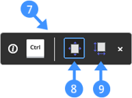
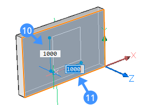
* Click the HKA field in the Status bar to toggle the display of the Hot Key Assistant.
- Do one of the following to place the selected window or door using the
dynamic dimension fields:
- Hit the TAB key to select one of the dynamic dimension fields, then
type a value and hit the TAB key to lock the dimension.
The locked dimension turns red (12).
- Hit the TAB key to select one of the other dynamic dimension fields,
then type a value and hit the TAB key to lock the dimension. The locked dimension turns red (13).
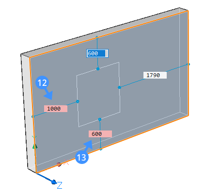
- Hit the TAB key to select one of the dynamic dimension fields, then
type a value and hit the TAB key to lock the dimension.
Using the components panel
See: Insert a window from the Components Panel into your drawing.
Procedure: editing the parameters of an insert
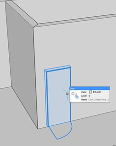
- Select any door or window in the drawing. The current values of the various
parameters display in the Parameters section of the
Properties panel. In the following illustration,
window parameters are shown in the Properties
panel.
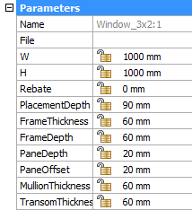
- Select a parameter you want to change, then type a value in the settings field.
Moving an insert
- Using Distance fields.
- Using Push/Pull
- Using the Manipulator
- Select the insert in the model. Current distances from the insert to the nearest parallel faces of the parent solid display:
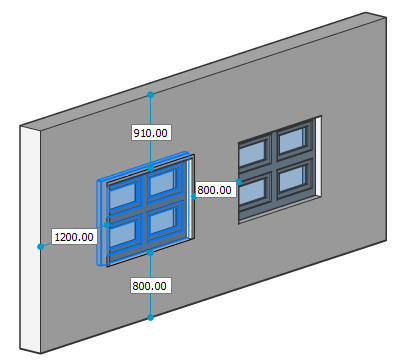
- Double click a distance field, then type a value and press Enter.
- Hover the cursor over the top or the bottom inner face of the opening (14) made
by the insert to move the insert vertically. Or to move the insert horizontally,
hover the cursor over the left or the right inner face of the opening (15) made
by the insert.
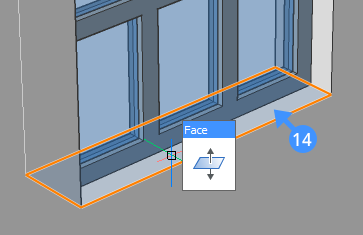
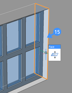
- When the face highlights, select DmPushPull from the
Model tab of the Quad.
The insert will move vertically if the top or bottom inner face is highlighted.
The insert will move horizontally if the left or right inner face is highlighted.
- Do one of the following to complete the moving insert process.
- Specify a point.
- Type a distance in the dynamic dimension field.
- Use Adaptive Grid Snap of the Ruler.
Procedure: using the Manipulator
Select the insert by holding the left mouse button down a bit longer. Set the MANIPULATOR system variable to 2.
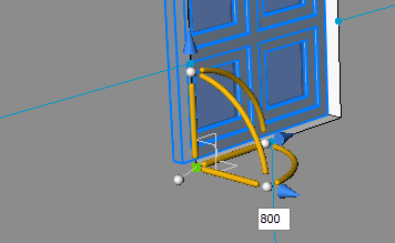
- Hover over the vertical or horizontal axis trigger zone of the
Manipulator.The axis highlights and the rest of the Manipulator fades.
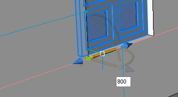
- Click to start the movement operation.
The window moves dynamically or if you hold down the Ctrl key creates a copy of the selected insert.
The Ruler displays.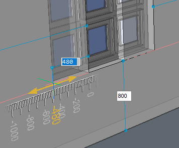
- Do one of the following:
- Type a distance in the dynamic dimension field.
- Use Adaptive Grid Snap of the Ruler.
Copying Inserts
- Hover over the insert. When the insert highlights, choose Insert BIM Component in the Model command group in the Quad.
- You are prompted: Select insertion point or [Edit inserted entity/Rotate component/set Base point/Name/insertion Type/Flip/mUltiple/Change target 3d solids] <0, 0, 0>:
- Optionally choose the Multiple option to insert multiple copies.
- Proceed with the Inserting Windows and Doors procedure from step 2 on.
Copying an insert in a solid
Procedure: copying an insert on the wall face
- Select an insert using the BIM Insert tool.
You are prompted: Select insertion point:
- Place the insert on the wall face.
The insert should align with the wall face.
- Next, hover over the insert to create a copy of it. When the insert highlights,
choose Copy in the Modify command
group in the Quad.
You are prompted: Enter base point [Displacement/ mode] <Displacement>:
- Pick a point in the drawing area.
You are prompted: Enter second point <Use base point as displacement>.
- Type a displacement distance from the coordinates of the base point.Note: Displacement specifies the distance to position the copy.
You can use the dynamic dimension fields (16,17) to specify the displacement.
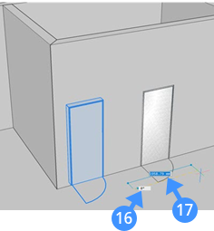
You are prompted: Enter second point [Undo/Repeat/Exit].
- Optionally, use the Repeat option to create multiple copies of the insert keeping the displacement distance of each copy same.
- Press Enter to accept the copying.
Replacing an insert
Use the BMREPLACE command to replace an insert.