Modeling a Corridor
Commands
CORRIDOR, CORRIDORTEMPLATE, CORRIDORTEMPLATEELEMENT, CORRIDOREDIT, CORRIDOREXTRACT.
Overview
In BricsCAD, Corridors that follow a certain 3D alignment are created using the Corridor tool.
About Corridor
A Corridor is a BricsCAD Civil drawing object used for modeling three-dimensional linear objects such as roads, railway, retaining walls, and bridges. It principally consists of a 3D alignment of the linear object and its typical cross-section – which is called Corridor Template in BricsCAD.
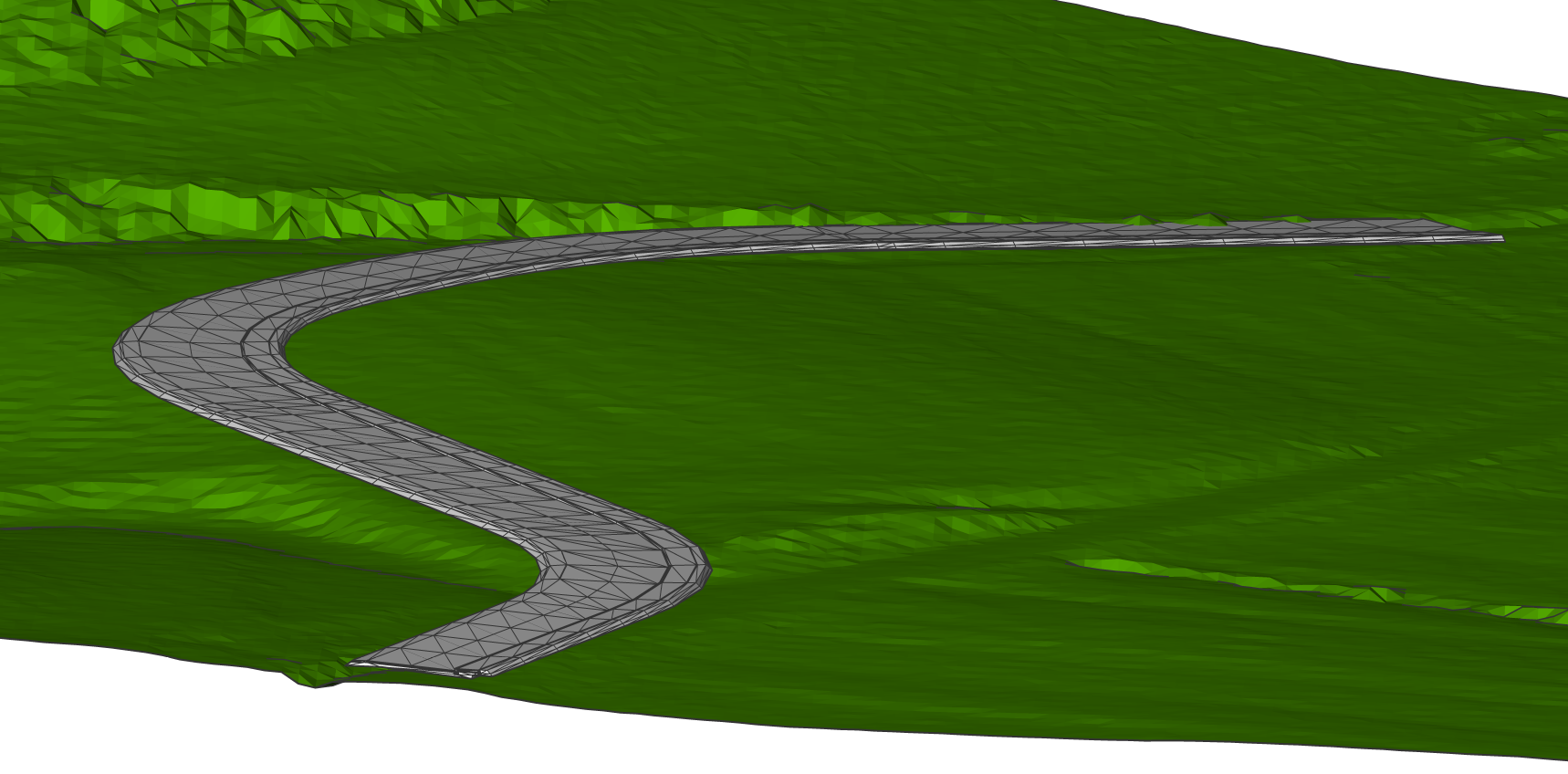
The CORRIDOR command enables you to create a Corridor, based on a Corridor Template, that follows a 3D alignment on a certain topographical surface.
About Corridor Template
In BricsCAD, a Corridor Template entity represents the framework to append a collection of template element objects. The command CORRIDORTEMPLATE enables you to create a corridor template entity and append one or more template elements to it.
About Corridor Template Element
In BricsCAD, a Corridor Template Element entity defines the geometry of a component used in a corridor section. The CORRIDORTEMPLATEELEMENT command enables you to create a corridor template element from closed polylines.
About Corridor Extract
The CORRIDOREXTRACT command is used to generate meshes, solids, polylines or outer boundaries from an existing Corridor.
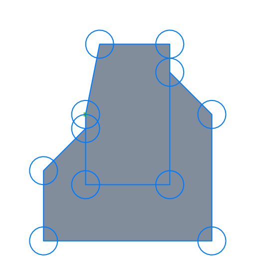
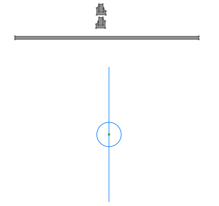
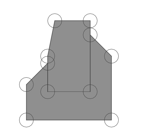
Procedure: Creating a template element of kerb
- Open an empty drawing.
- Draw closed polylines representing road kerb.
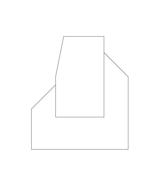
- Launch the CORRIDORTEMPLATEELEMENT command in the Command line.
- Select polylines representing kerb.
- Pick one of the polyline vertices, the base point position can also be changed
afterward.
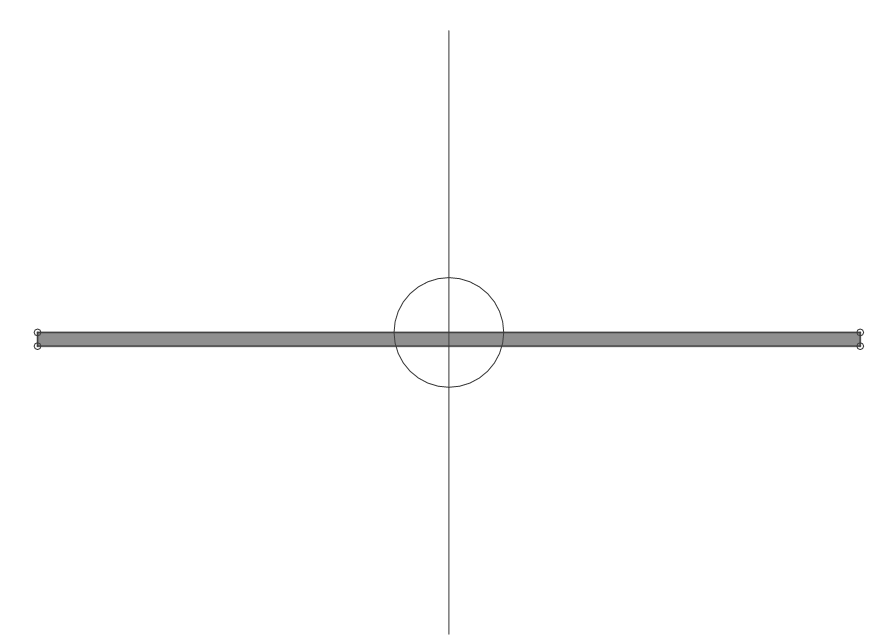
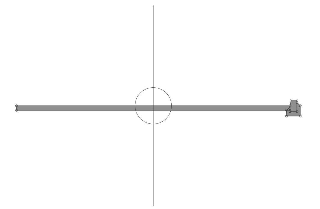
Procedure: Creating a template of road cross-section with asphalt layer and left and right kerb
- Open the drawing file that contains a collection of template elements.
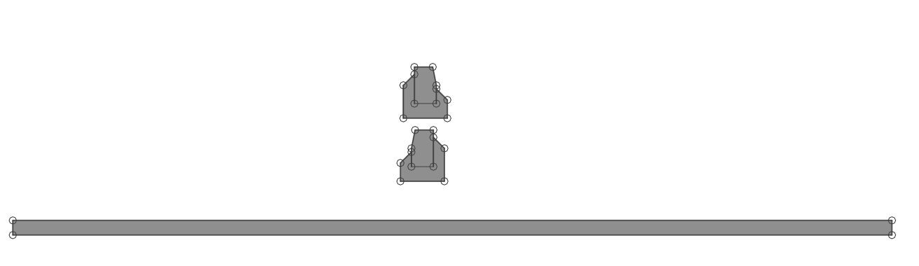
- Launch the CORRIDORTEMPLATE command in the Command line.
- Pick a point in the drawing where you want to create a corridor template.
- Launch the CORRIDORTEMPLATE command in the Command line.
- Select the Add template element option in the Command line.
- Select the template element representing the asphalt layer.
- Select corridor template or template element point: (select the template)
- Launch the CORRIDORTEMPLATE command in the Command line.
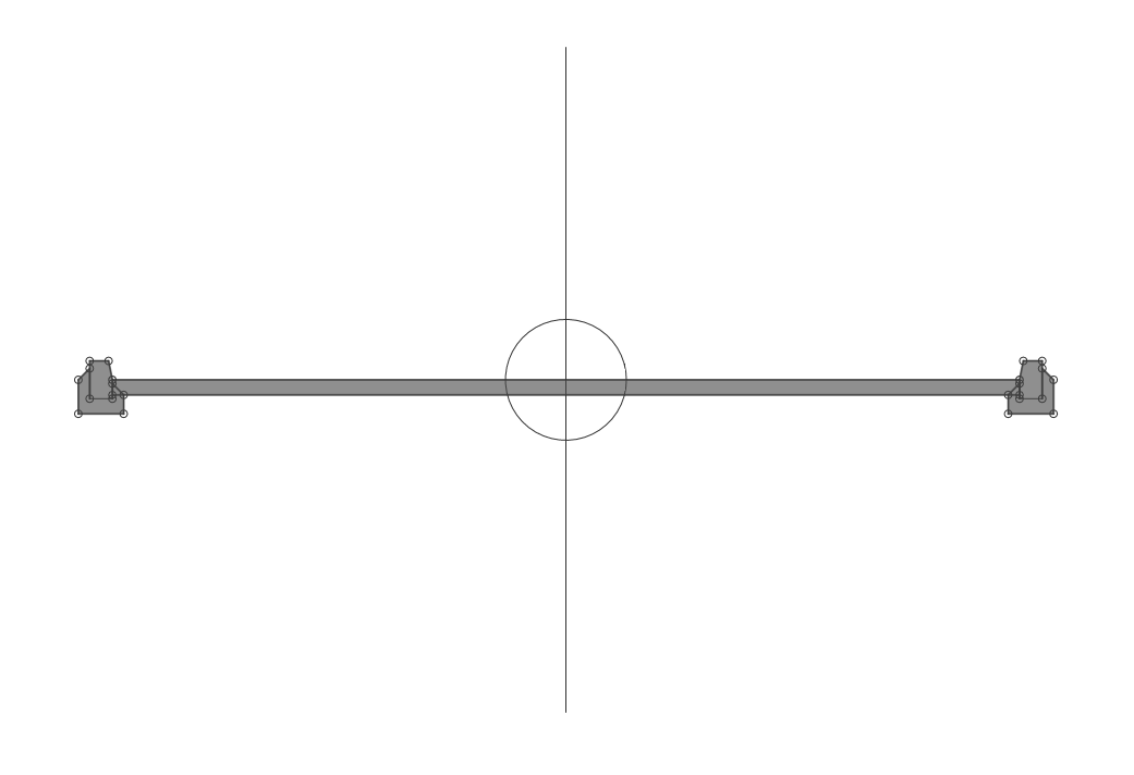
- Select the Add template element option in the Command line.
- Select right top template element point of asphalt layer.
- Select template element representing right kerb.
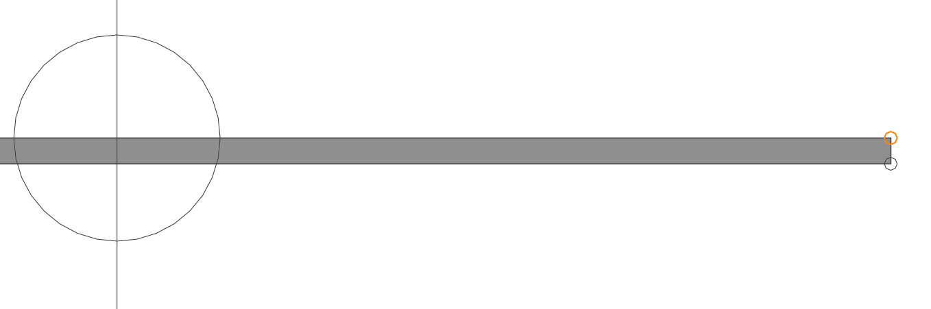
- To add a kerb to the left side, repeat the steps described in points 9, 10, 11.
By selecting the left kerb and left top point of asphalt layer this time.
Procedure: Creating a road corridor
- Open the drawing file that contains the TIN Surface (1), 3D Alignment (2) and
Corridor Template (3).
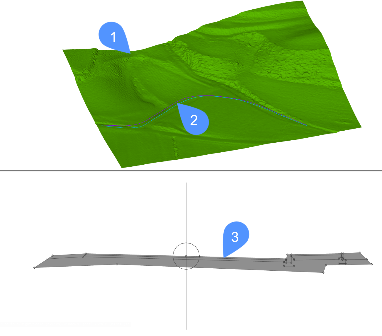
- Launch the CORRIDOR command in the Command line.
- Select 3D alignment (2) used as a corridor baseline.
- Select corridor template (3).
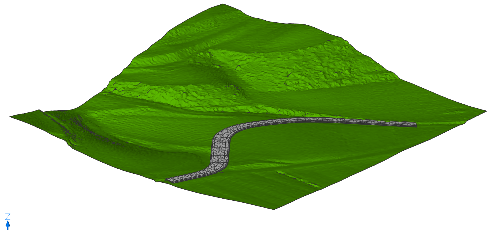
- Enter region start station. Press ENTER to start from beginning or type any station where you want your corridor to start.
- Enter region end station. Press ENTER to create corridor to the end of selected
alignment or type any station where you want your corridor to end.
About Corridor Edit
The CORRIDOREDIT command adds or removes regions from an existing Corridor.
Procedure: Editing a corridor
- Open the drawing file that contains the corridor you would like to edit.
- Select the 3D alignment that the corridor has as a reference and move the grip
points to edit the corridor horizontally.
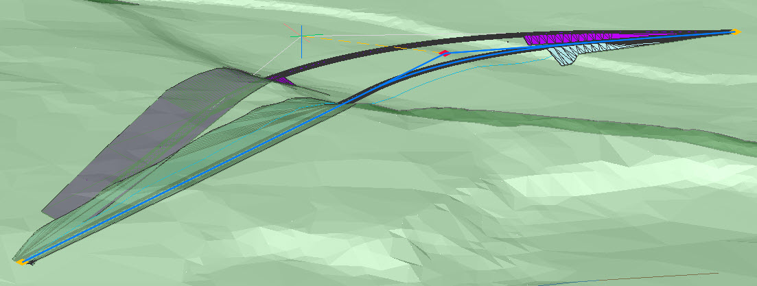
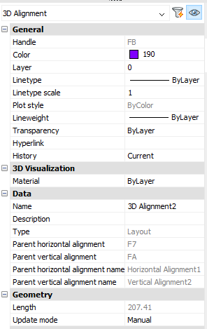
- To edit the corridor vertically, select the 3D alignment that the corridor has
as a reference and open the Properties Panel. Set the Update
mode to Manual. Extra grip points will appear.
- Move these grip points to edit the corridor vertically.
- Press ENTER and you have finished your edited corridor.
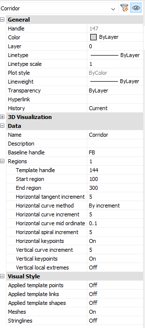
Displaying the properties of a Corridor
- Select the Corridor.
- The properties of the Corridor are displayed in the Properties panel.
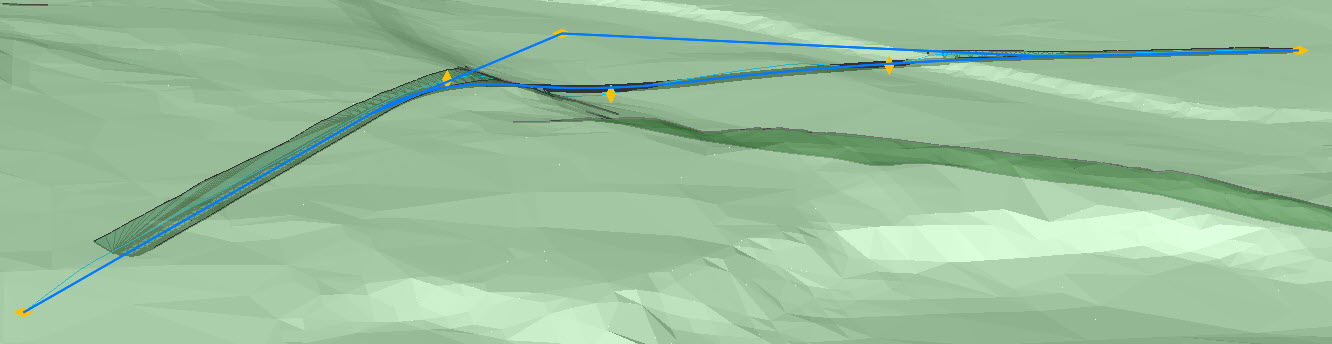
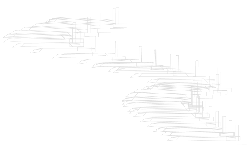
- Applied template points
-
Represents the corridor with template element points.

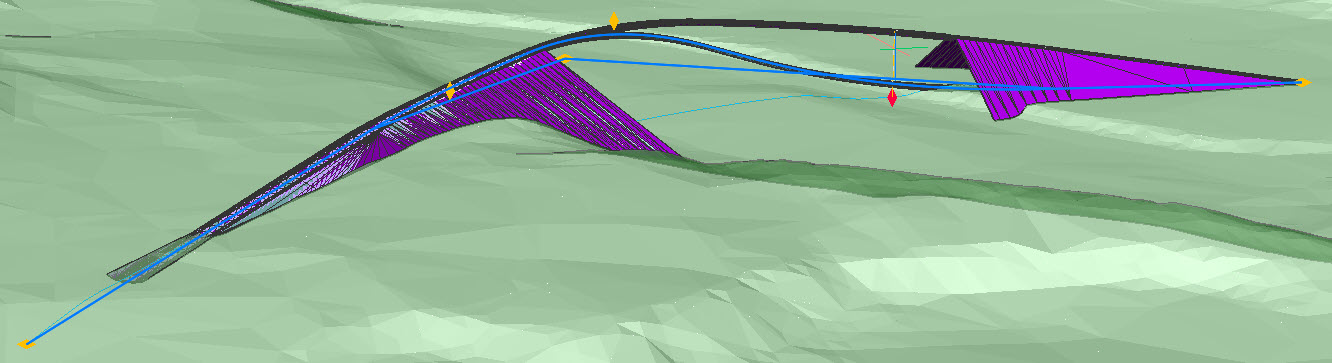
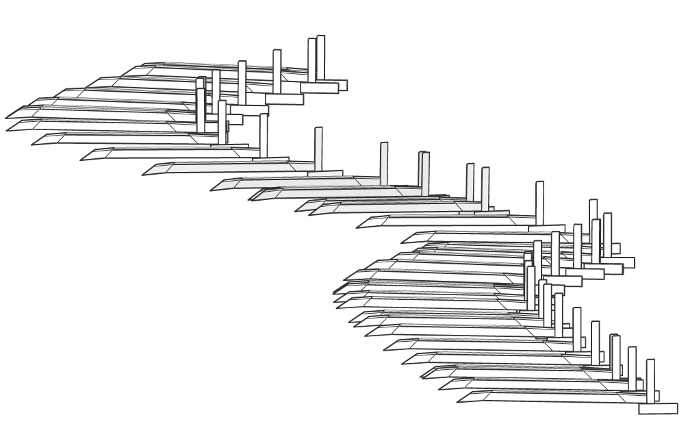
- Applied template links
-
Represents the corridor with template element links.
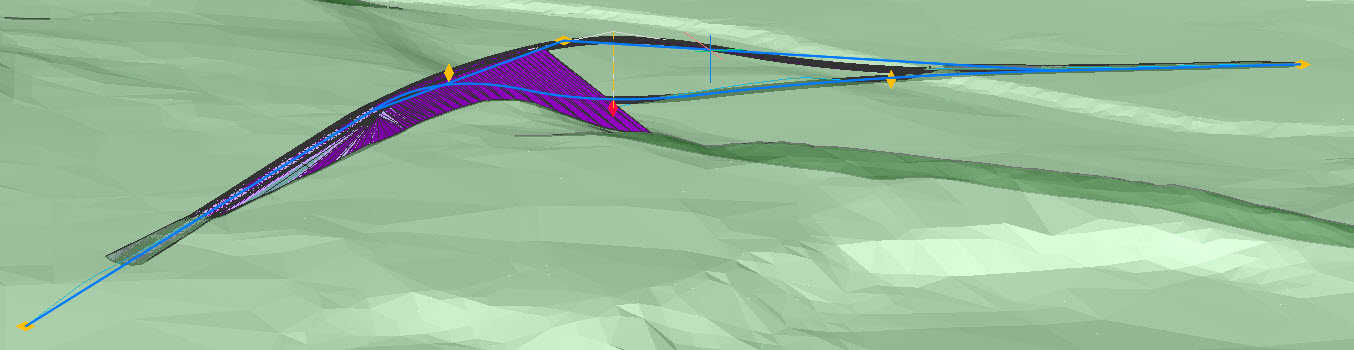
- Applied template shapes
-
Represents the corridor with template element shapes.
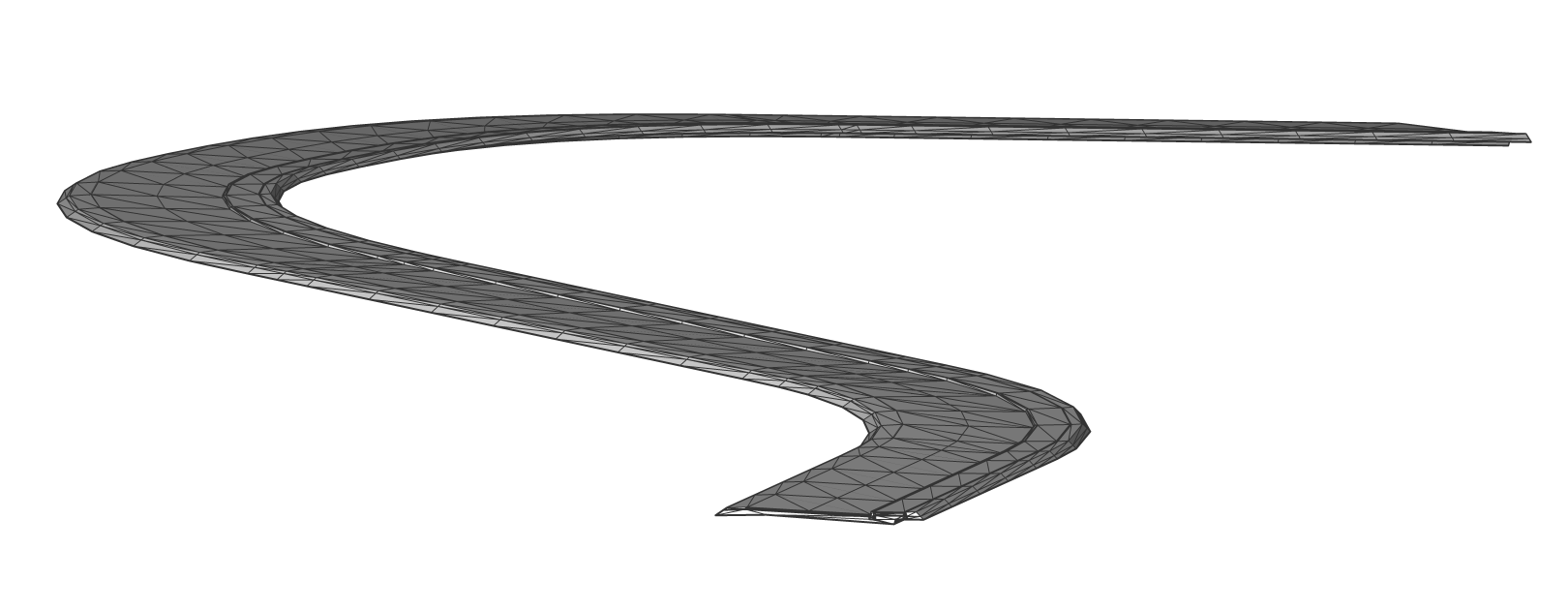
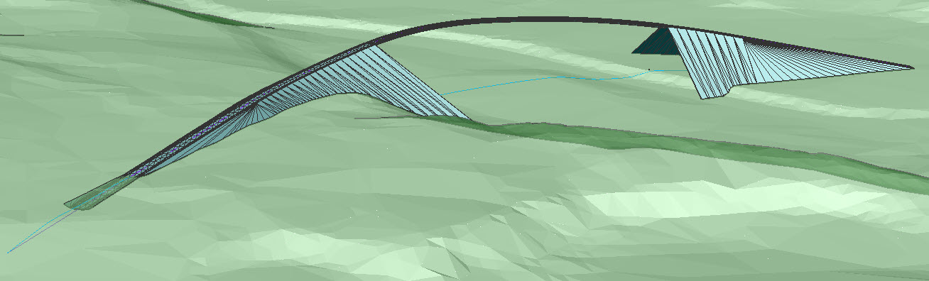
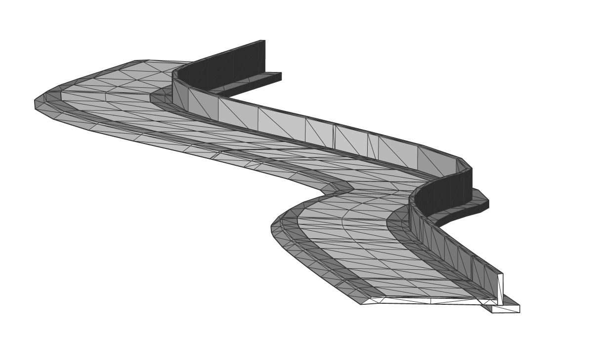
- Meshes
-
Represents the corridor with meshes.
- Stringlines
-
Represents the corridor with lines connecting the template element points along the corridor.