Design documentation
Sections
Activate SectionView
This new command allows you to look at the model from a section plane's perspective, without generating the section. This view allows you to manipulate the 3D model from a 2D point of view. To exit the active view, just orbit around the model.
Open BimSections
When switching to the model from a sheet view using the BIMSECTIONOPEN command, the model is rotated and zoomed in to the same zoom level as the sheet view.
Available properties and property values display in the filter parameters form.
The BIMSECTIONOPEN command now allows you to transition between the sheet viewport and drawing model seamlessly at the same zoom level, without the need to re-orientate yourself and the model to where you have been working earlier on the sheet.
When you switch between a sheet viewport to the drawing model using the updated BIMSECTIONOPEN command, the drawing model displays and orientates itself to the same zoom level as in the sheet viewport, regardless of the scale of the Standard Scale or Annotation Scale of the drawing or viewport.
Update BimSections
The associative data for 3D solids, needed for section generation and tagging of the section results by the BIMTAG command, are generated automatically in BricsCAD BIM V21 as you model, unless the new GENERATEASSOCATTRS (Generate Associative Attributes) system variable is set to Off.
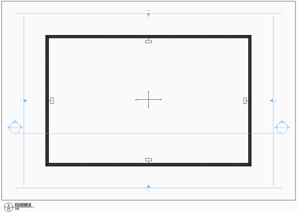
Interior Elevations
Since Rooms in V20 and older are now deprecated and replaced by Spaces, the Interior option of the BIMSECTION command now supports Spaces.
Tags
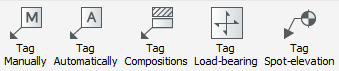
Automatically generated tags can have an offset, which is defined through the Offset attribute in TagTypeToStyle.xml found in the folder. If the offset is not specified, the center of the tag block will be used.
Similarly, automatic and manually placed tags can be rotated if the autoRotation attribute is set to true in TagTypeToStyle.xml.
Tag Load-bearing
Load-bearing tags is only applicable if the load-bearing direction of the slab has already been set. Refer to the BIMSETLOADBEARINGDIRECTION command for more information.
Tag Spot-elevation
The spot elevation level tag displays the actual elevation of a selected point of a BIM object in a section view. The height is measured relative to level 0.
Tags in general
On Paper Space, click Tag Load-bearing from the ribbon and pick point on a sectioned BIM element as prompted. You will be prompted to pick a point on your desired sectioned BIM element or to change the current mleader style settings, like how you set BIMTAG in V20.
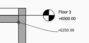
Like all other BIM tags, they are customizable multileader blocks. Therefore, for example, Spot Elevation tags can be further adjusted to suit your graphic and information preferences.
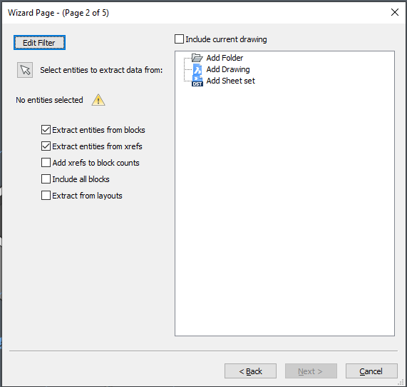
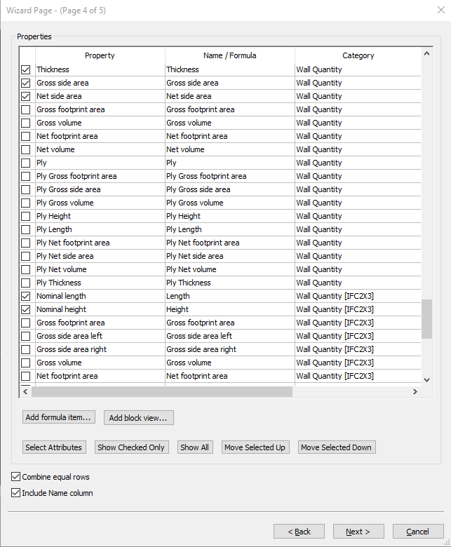
Data Extraction
The DATAEXTRACTION command now allows you to include all blocks and also extract from layouts in the new filter rule settings. You can now extract composition and physical material data.
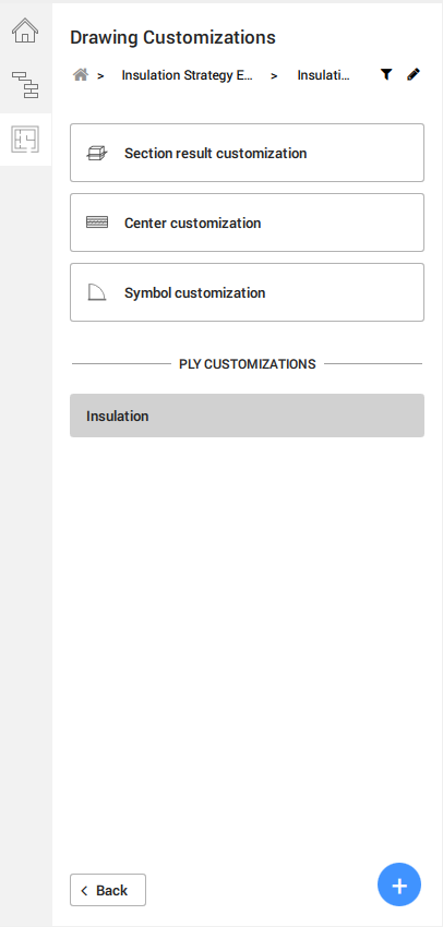
Drawing Customizations
Drawing Customization is a new tool that is available and only accessible from the panel. All the controls of Drawing Customizations are represented as graphic icons within the User Interface panel, such as the + symbol in a blue circle to create a new template. You can duplicate, rename or delete your customization templates.
Drawing Customization templates are stored within the Customization folder located in the SUPPORTFOLDER, under .
Each customization template is saved as an individual folder which contains in its basic form Settings.dwg, a Filter.json and a New customization.json files. The folder will also contain any external symbol sources which you have created new using the Create New buttons.

Entity Customizations
Entity Customizations refer to the visibility settings of how you would like to have your elements in your model drawing to look like.
The section result customization displays a series of controls with drop-down values from the Styles tab for more specific control of the section result graphics. You can override the entities’ hatches via the Appearance Override with preset or custom Physical Materials available in your project.
For the Symbol Customization settings, you can find an input dialog to specify your desired external symbol drawing in .dwg format. There are additional buttons to allow you to edit the selected symbol drawing or to create a new .dwg symbol.
You can further apply your saved Styles to specific layers within your external symbol source, thereby allowing you to retain a general symbol drawing across several customization templates with different output results.
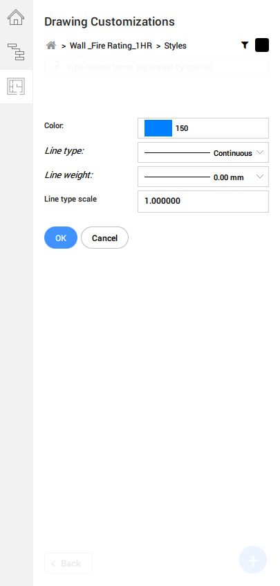
Styles
This is where your desired style options like Lineweight, line colors, etc, are stored and will appear as drop-down options in the Entity Customizations and Center Customizations settings as shown in the previous section above.
The operation of the Styles tabs is like how Entity Customization tabs can be controlled.
Filter Rules
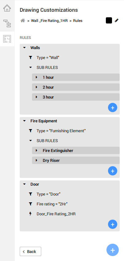
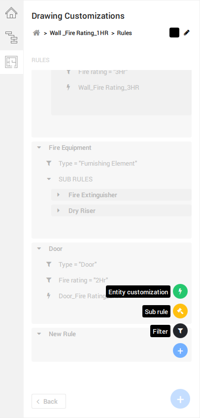
Adding and editing a filter parameter will lead you to a prompt, where the options of filter property is determined by the BIMPROPERTIES imported in the namespace settings.
To end and legitimize a filter rule, the entity customization value must be added and filled in. The options available in the drop-down selection reflects the existing customizations tab available in the Entity Customization page.