Create and edit alignments
Commands
ALIGNMENT, ALIGNMENTEDIT, ALIGNMENTVIEW
Overview
In BricsCAD, alignments are created using the Alignment tool. Alignment is the route of the linear objects, defined as a combination of lines and curves that are viewed as one object.
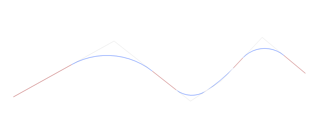
About ALIGNMENT
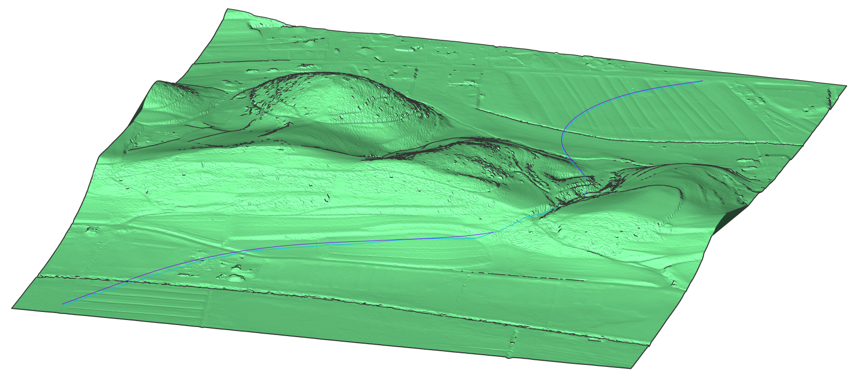
Alignment is a reference system used to position linear objects, like roads, railways, pipe networks, streets, retaining walls and bridges, in space. An alignment is represented with horizontal, vertical 2D curves, resulting in 3D alignment.
- Horizontal alignment
-
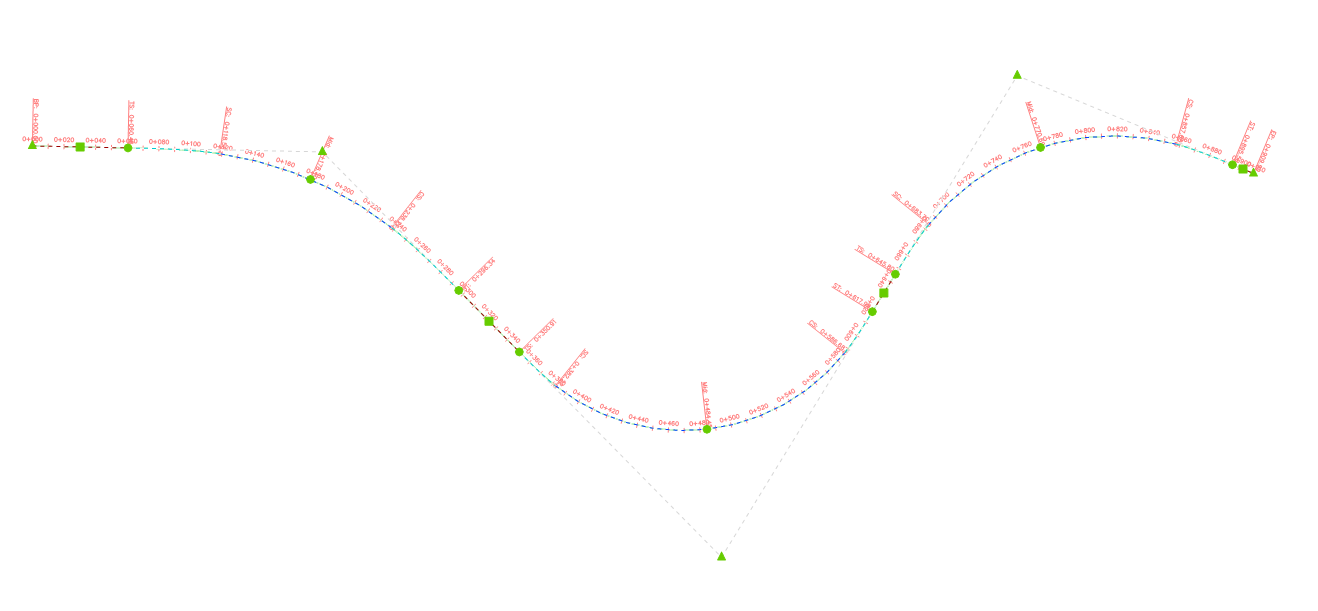
Horizontal alignment is a 2D curve that is needed to precisely position linear objects in a horizontal direction. It becomes defined by the Points of Intersection (PI). Horizontal alignment is the horizontal trace on your TIN Surface which is used to generate the height profile and vertical alignment. A single horizontal alignment can have multiple vertical alignments. The horizontal alignment will appear under the surface.
- Vertical alignment
-
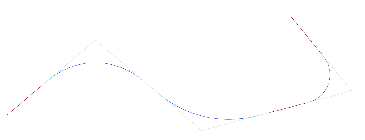
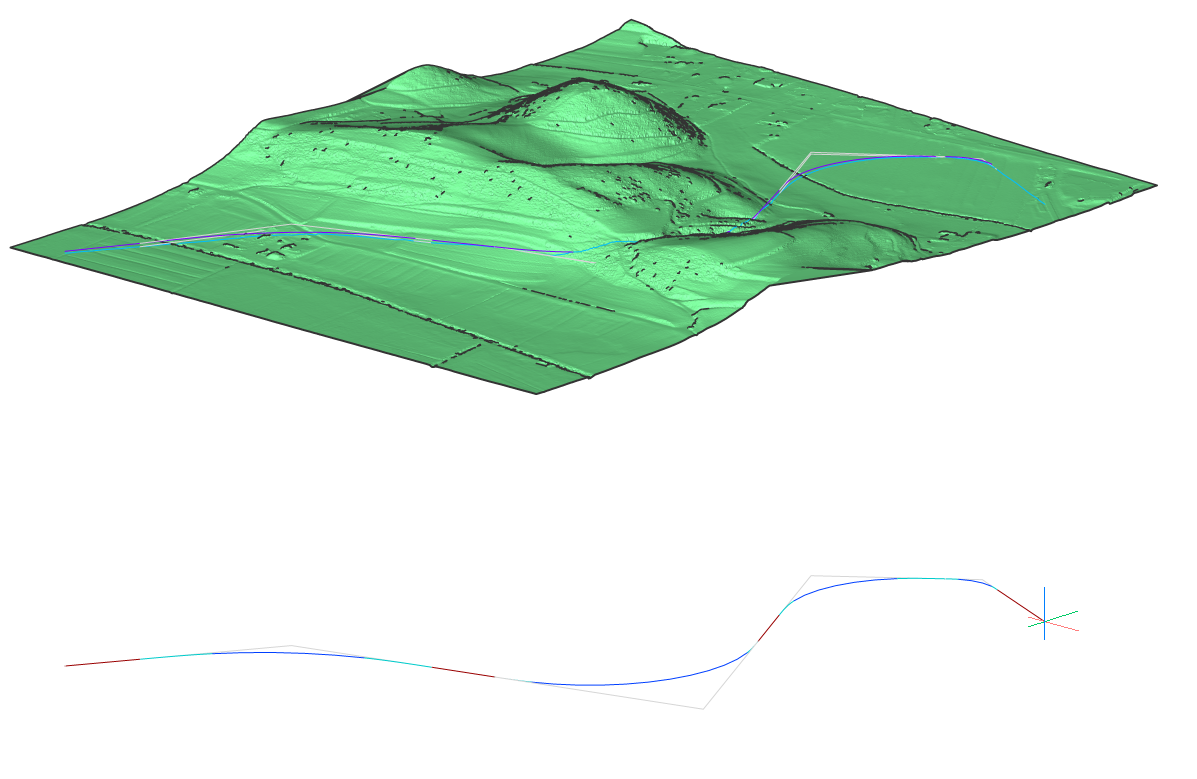
A vertical alignment is needed to precisely define a linear object in the vertical sense. The horizontal path defined by the horizontal alignment corresponds with a vertical profile of the TIN Surface. By defining Points of Vertical Intersection (PVI) on these vertical profiles of the target surfaces, the new 2D curve defines the vertical alignment.
- 3D alignment
-
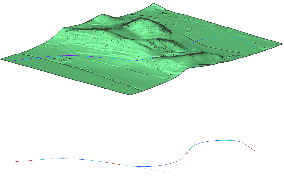
A 3D Alignment is a 3D polygonal curve defined by the horizontal and vertical alignment.
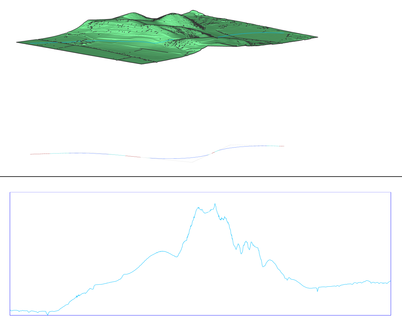
Procedure: Creating an Alignment
- Open the drawing file that contains a TIN Surface.
- Launch the ALIGNMENT command in the Command line.
- Select Horizontal alignment in the Command line.
- Select the TIN surface.
- Pick the horizontal alignment PI points on your surface. Press ENTER when done.
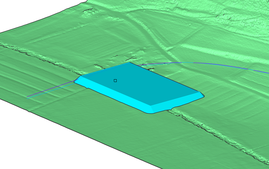
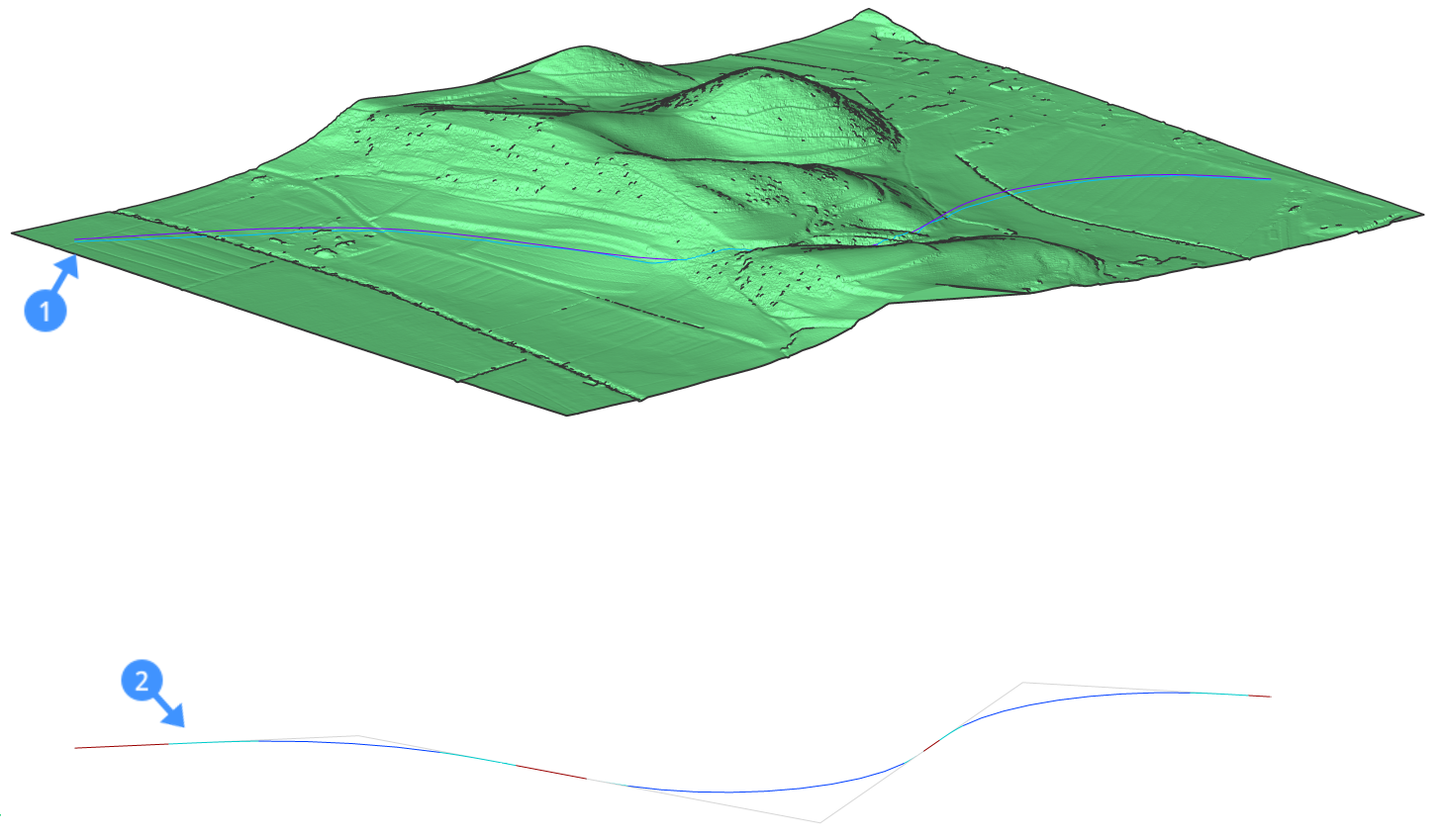
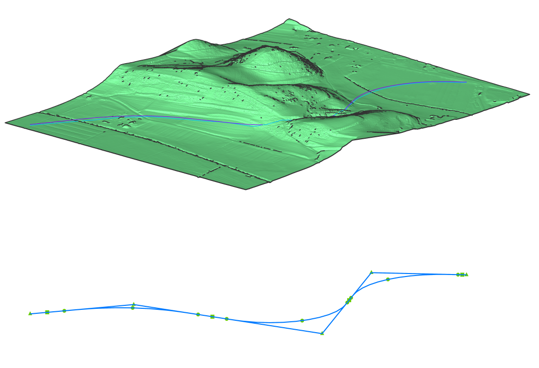
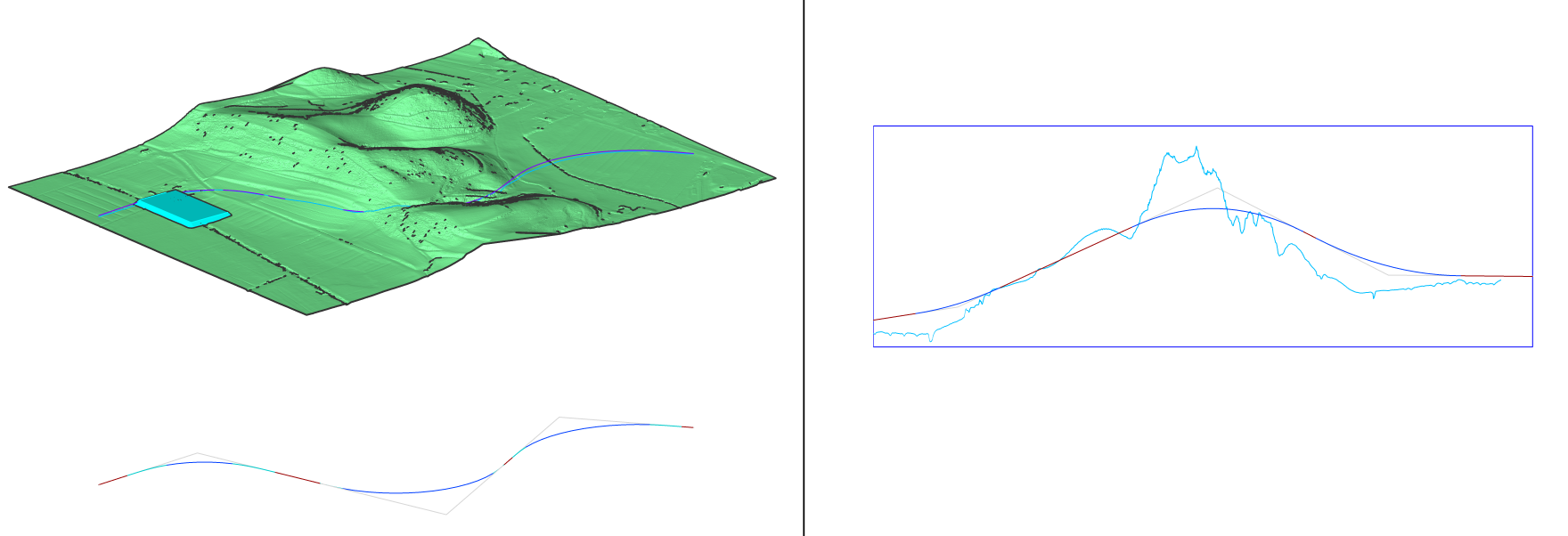
Your 3D alignments (1) and horizontal alignment (2) are now generated.
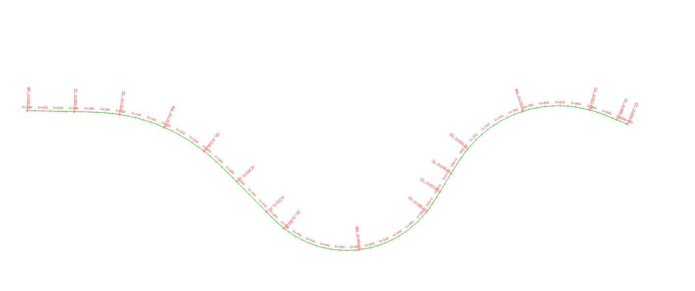
Procedure: Creating a Horizontal Alignment without 3D alignments
- Open an empty drawing and launch the ALIGNMENT command in the Command line.
- Select Horizontal alignment in the Command line.
- Select the Pick Pi point option in the Command line.
- Pick the horizontal alignment PI points. Press ENTER when done.Your horizontal alignment is now generated.
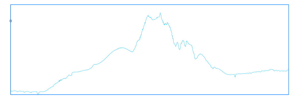
About Vertical Alignment View
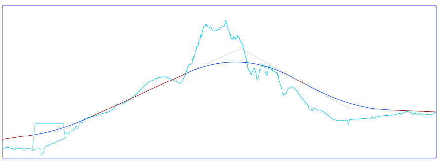
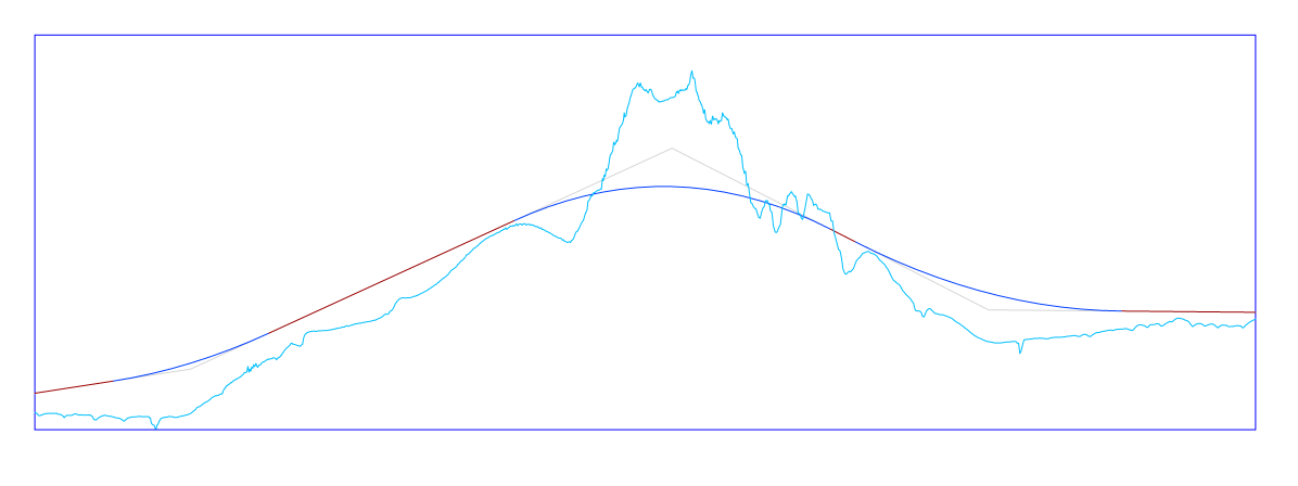
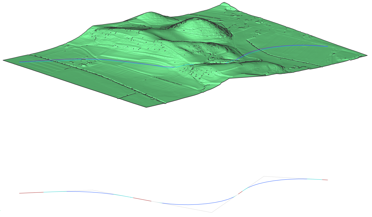
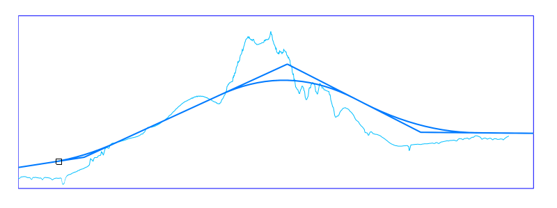
The horizontal alignment creates a vertical section of the target surface. This 2D curve can be displayed in a separate viewport inside your model space using the command ALIGNMENTVIEW.
Procedure: Creating a Vertical Alignment View
- Open the drawing file that contains a TIN Surface, Horizontal Alignment and 3D
Alignments.
- Launch the ALIGNMENTVIEW command in the Command line.
- Select a horizontal or 3d alignment in the drawing.
- Pick a point as origin for the vertical alignment view. Your vertical alignment view is now generated.
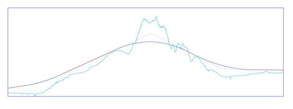
Procedure: Creating a Vertical Alignment
- Open the drawing file that contains a TIN Surface, Horizontal Alignment and
Vertical Alignment View.
- Launch the ALIGNMENT command in the Command line.
- Select the Vertical option in the Command line.
- Select vertical alignment view in the drawing.
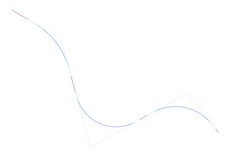
- Pick the vertical alignment PVI points. Press ENTER when done. If you want to go
one step back, use Undo. Automatic 3d alignment option generates design vertical
alignment automatically. Your design vertical alignment is now generated.

Procedure: Creating an Alignment from Civil 3D drawing
- Open the drawing file from Civil 3D that contains a Civil 3D Alignment.
- Launch the ALIGNMENT command in the Command line.
- Select the create from Civil 3d alignment.
- Select the civil alignment in the drawing and press ENTER. Civil 3D alignment is converted to BricsCAD Alignment.
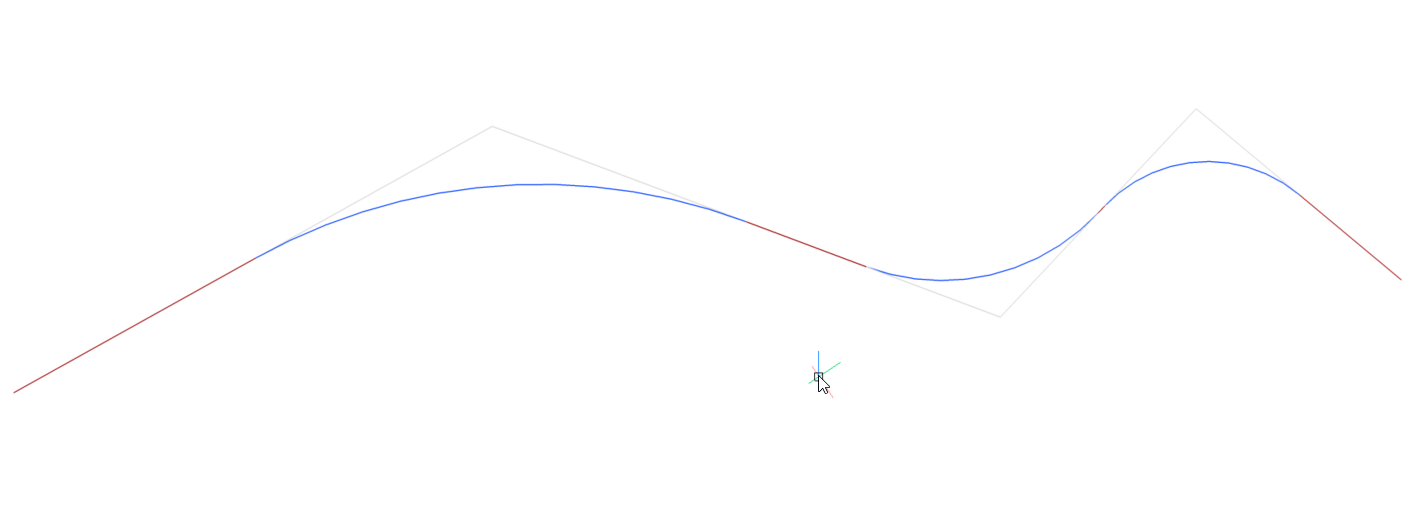
About ALIGNMENTEDIT
After creating an alignment, you can continue a horizontal or vertical alignment, add or delete PV/PVI points or change the TIN Surface using the command ALIGNMENTEDIT. The 3D alignment will be updated automatically.
Procedure: Continuing a horizontal alignment with ALIGNMENTEDIT
- Draw a horizontal alignment following the steps from the Procedure: Creating an alignment.
- Type ALIGNMENTEDIT in the Command line.
- Select the horizontal alignment you want to edit.
- Select points on your surface to continue your existing alignment.
- Press enter when finished. You have now continued your horizontal alignment. The
3D alignment will be updated automatically.
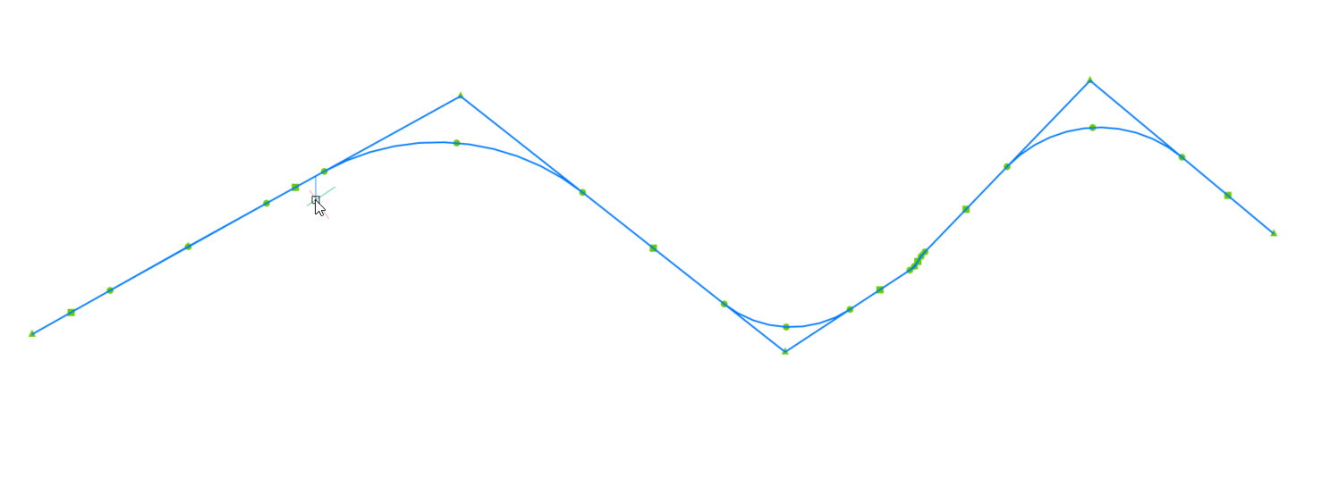
Procedure: Adding PI to an existing horizontal alignment
- Type ALIGNMENTEDIT in the Command line.
- Select the horizontal alignment you want to edit. You are prompted: Pick a point to continue alignment or [Add Pi/Remove Pi/change Tin surface].
- Select Add Pi in the Command line.
- Pick point to add new PI.
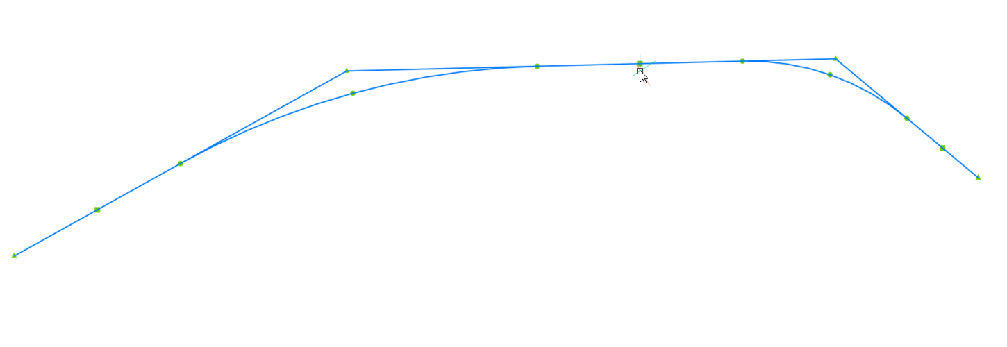
Procedure: Removing PI to an existing horizontal alignment
- Type ALIGNMENTEDIT in the Command line.
- Select the horizontal alignment you want to edit.
- Select the Remove Pi option in the Command line.
- Pick a PI point to remove.
Procedure: Adding additional TIN Surface to Vertical alignment view
- Open the drawing file that contains a TIN Surface, Alignments, Vertical
Alignment View and grading.
- Launch the ALIGNMENTEDIT command in the Command line.
- Select the change Tin surface option in the Command
line.
- Select the TIN surface to add.