Drag and drop the desired profile from the BIM
Profiles panel to the model space.
Note: This command works in the same way as the LINE
command.
To define the starting point and the following point(s) click in the model
space or use the dynamic dimension fields.
Press Enter to end the command.
Note: BricsCAD doesn't automatically generate the
connections between the different segments because the chosen
profiles are structural steel.
About BIMSTRUCTURALCONNECT
The BIMSTRUCTURALCONNECT command automatically generates connections for
profiles.
For more information about this command, visit the Command Reference article
BIMSTRUCTURALCONNECT.
Making a structural connection to linear solids
Select the profiles you want to connect with.
Launch the BIMSTRUCTURALCONNECT command. by typing it in the Command line or
select StructuralConnect in the
Model tab in the Quad.
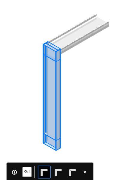
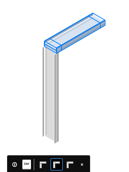
When the Hot Key Assistant is on (HKA on the
status bar), a widget (as displayed below)
appears on the screen. Tap the CTRL-key to cycle through the different
options.
Press Enter to accept the selected option and end the command.
About DRAG
The DRAG command makes it possible to alter a segment of a drawn profile without
losing the connection to other segments.
For more information about this command, visit the Command Reference article
DRAG.
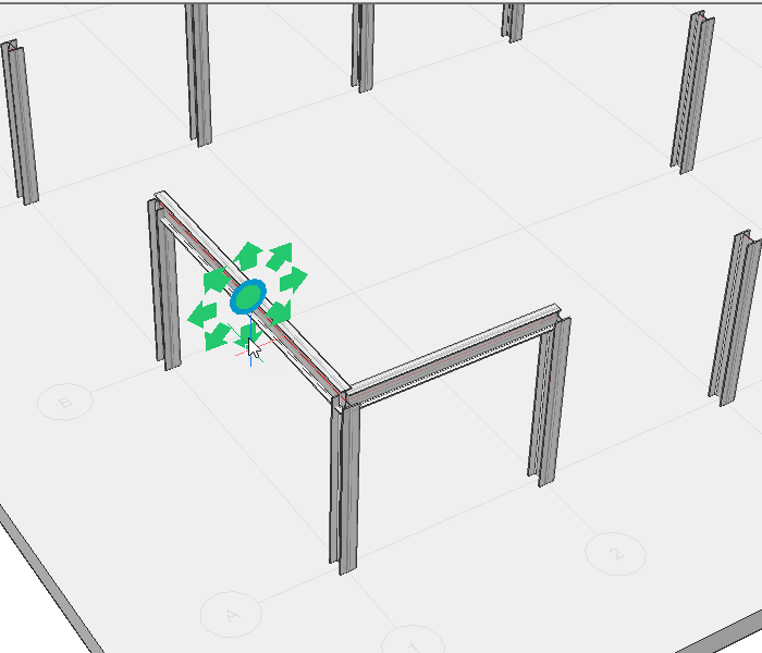
Altering the positioning of segments
Note: This only
works if the connections were created with the BIMSTRUCTURALCONNECT
command.
Set the value of DISPLAYSIDESANDENDS system variable to 1.
Select a face perpendicular to the section of the profile.
Launch the DRAG command.
Click the mouse to set a new position for the segment. Or use the dynamic
dimension field to enter a value for the displacement.
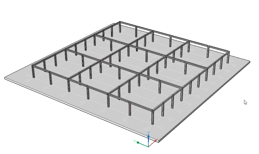
Procedure: use modeling tools to create a structural steel model
Draw a BimGrid as a base.
Launch the BIMGRID command.
Click a starting point and enter values into the dynamic dimension
fields.
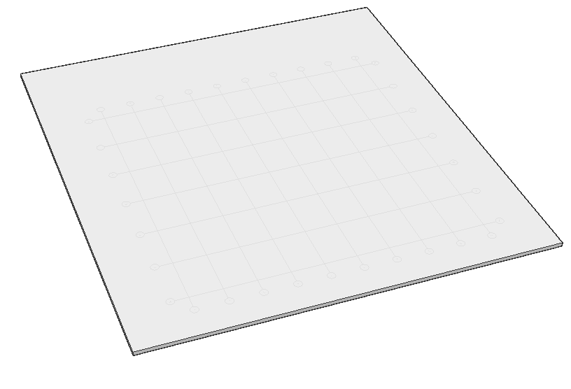
Draw a base slab underneath the grid.
Create a slab using the BOX command.
Ensure that the grid is entirely on top of the slab and that the axes of
your profiles are displayed.
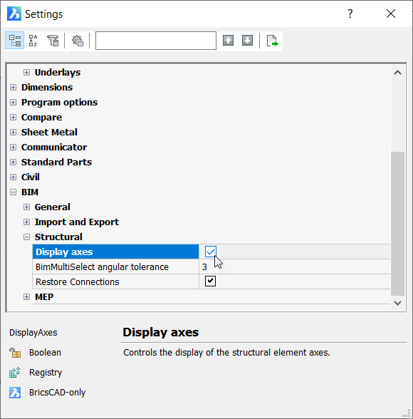
Go to the Settings dialog and under the BIM > Structural section. Ensure that Display Axes is
checked.
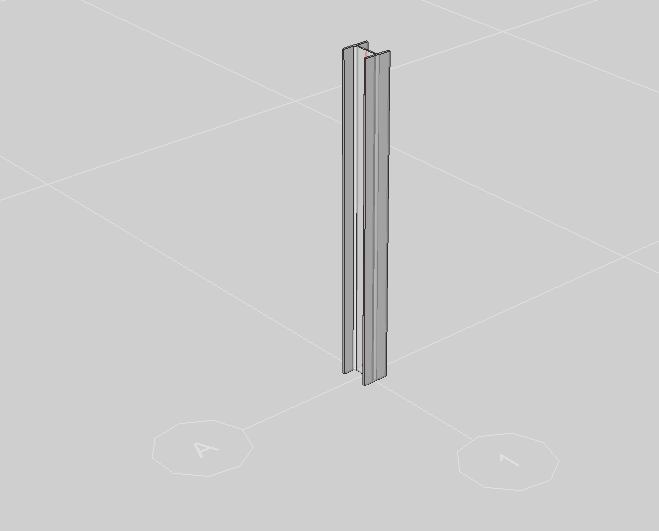
Open the Profiles panel and drag a structural steel
profile into your model. Start drawing at the intersection point of two grid
axes and draw vertically upward.
Note: To snap specific
points, make sure you have toggled on the different types of points you
want to snap in the context menu when right-clicking on
ESNAP.
Launch the BIMPROPAGATE command.
Select the slab as base solid and press Enter.
Select the column as your detail element and press Enter. BricsCAD will zoom
into the 3D detail. Press C to copy the column as a solid, not as a block.
Note: The default setting for BIMPROPAGATE is to
copy the object as a block.
Hit Enter.
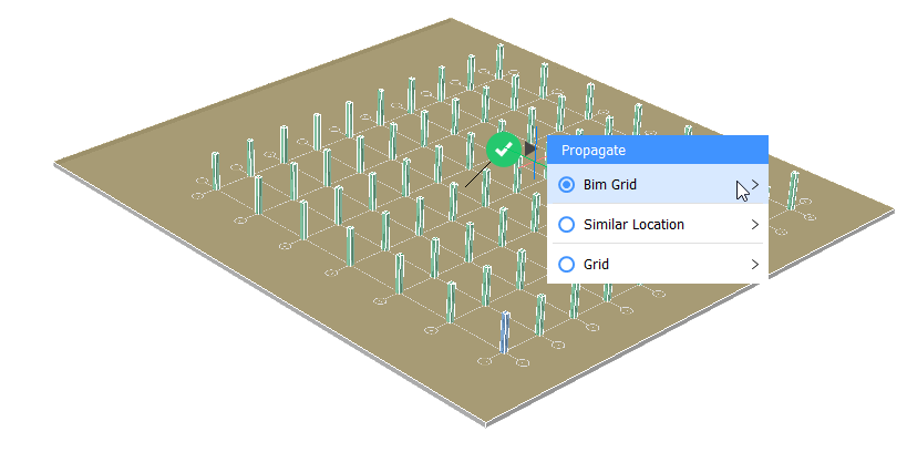
Note: BricsCAD automatically copies the beam
to every grid intersection. This is because you chose the floor slab
with a BimGrid as your base solid.
Hover over the green checkmark and click Bim Grid in
the dialog box.
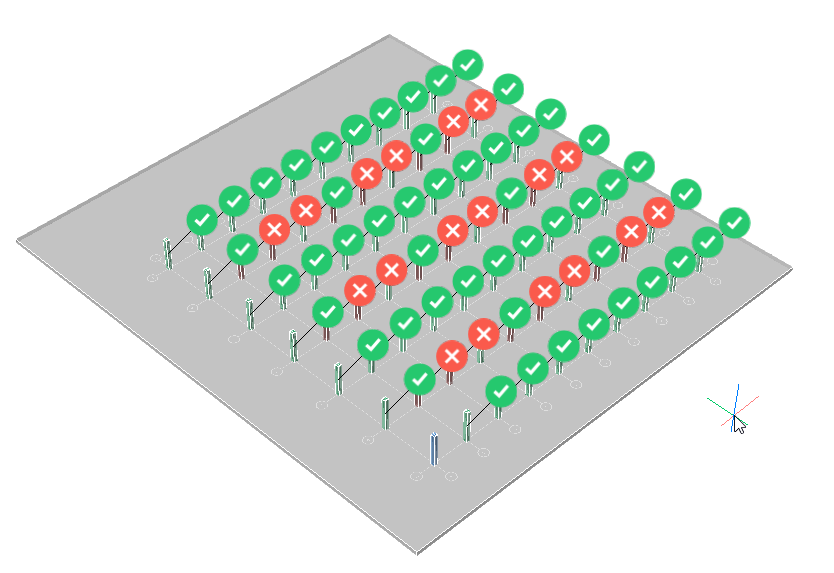
Click Explode. You can now manually toggle individual
suggestions to create the pattern of your choice.
Press Enter to accept and end the command.
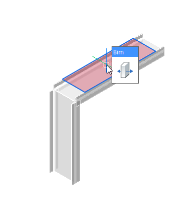
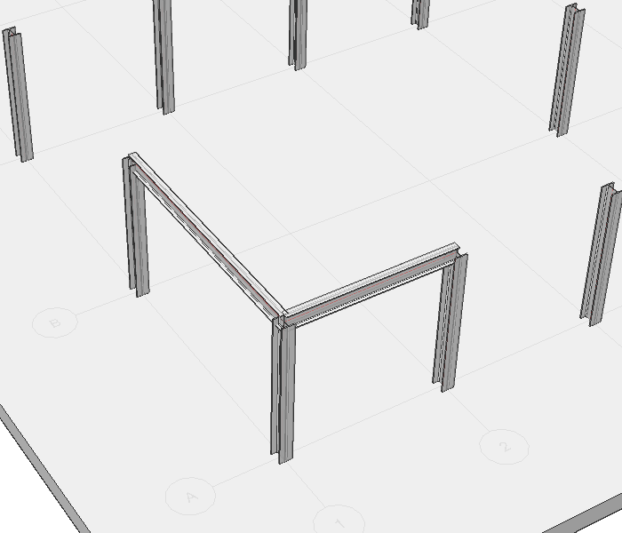
Create beams between the columns
Open the Profiles panel and drag a structural steel
profile into your model. To set the start and endpoints, click the top of
the column and then the next. Do this in both directions.
Note: If you want to turn your profiles to make the
flanges are facing upwards, press Q (from Quarter turn). The profile
will turn 90 degrees around its axis.
Drag and drop a beam profile from the Profiles panel onto
this beam. Give the second beam a large profile, as it has a longer
span.
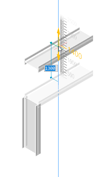
Select a beam and launch the BIMADDECCENTRICITY command to alter the
relative position of the axes of the beams.
Click the down arrow. The beam moves down in relation to its axis.
Press Enter to end the command.
Repeat steps 3-5 for the other beam.
Select the column and the two beams then launch the BIMSTRUCTURALCONNECT
command to make a simple connection. Press Enter to accept the default
option.
Repeat step 7 for the other 2 junctions.
Select the two columns connected to the beam in the Y-direction and launch
the BIMPROPAGATE command.
Select the beam in the Y-direction as the detail solid.
Press C to copy it as a solid, not as a block.
Press Enter.
Choose which suggestions to accept. Press Enter to accept and finish the
command.
Note: Suggestions are made at the bottom
of every column because the situation is symmetrical. You can toggle the
suggestions off.
Repeat steps 9 - 13 to create beams on the X-direction.
Note: You can use box selections to select all the lower
beams at once.
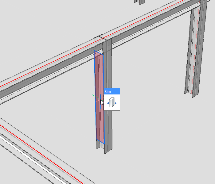
Move a Beam
Set the value of DISPLAYSIDESANDENDS system variable to 1.
Highlight the side face of the desired column and launch the DRAG
command.
Move the column to the desired position.
Note: The connections with the adjoining beams are
maintained.
Procedure: use the modeling tools to create a more detailed connection
Set the value of DISPLAYSIDESANDENDS system variable to 0.
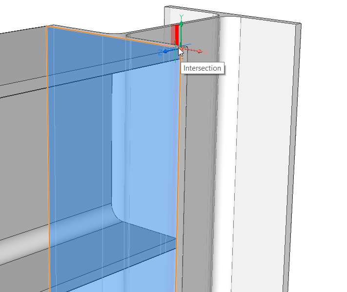
Launch the BOX command and hover over the side face of the column.
Press Shift once so that the face is highlighted in blue.
Now draw a plate on the flange of the column.
Select the beam and launch the SUBTRACT command.
Select the endplate and press Enter.
Select the face and launch the BIMIFY command from the Quad.
Note: You can also Classify the plate manually by Quad
selecting Classify Manually in the
BIM tab.
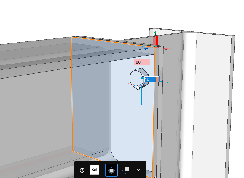
Open the Library panel and drag a bolt onto the
plate.
Note: You can position it precisely by
entering values in the dynamic dimension fields.
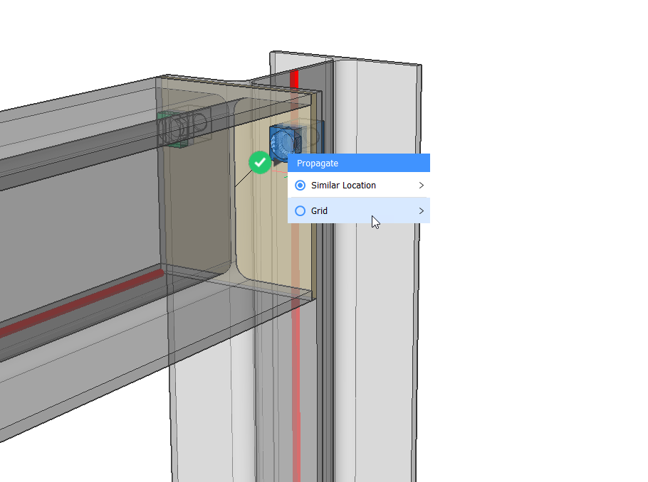
Select the plate and launch the BIMPROPAGATE command.
Select the bolt as the detail and press Enter.
Press Enter again and click on the blue question mark. It will turn into a
green checkmark.
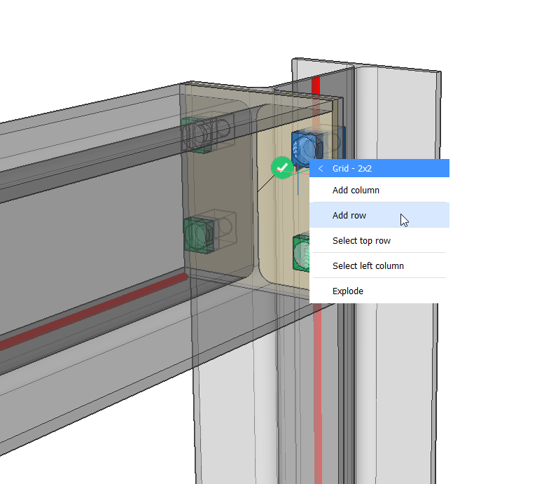
Hover over the checkmark and select Grid.
Add one row.
Press Enter to end the command.
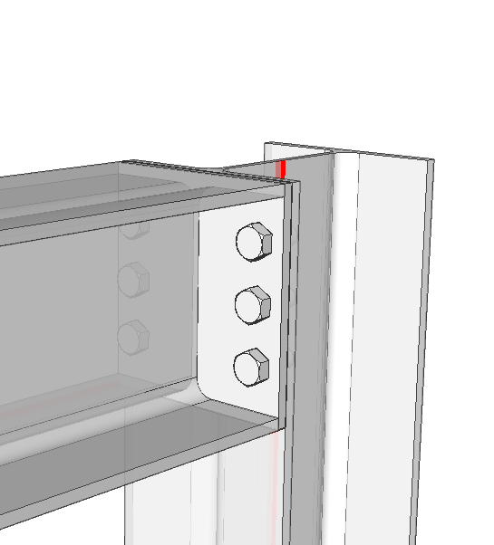
The detailed connection has now been created.
Procedure: using BIMSTRETCH to modify structural steel
Open a New drawing.
Open the Profiles panel by clicking on it on the
right-hand side of your screen.
Note: If the
Profiles panel icon isn’t visible yet,
right-click on the ribbon and check BIM Profiles
in the context menu under Panels.
Drag the profile you want to draw a structure with within the model
space.
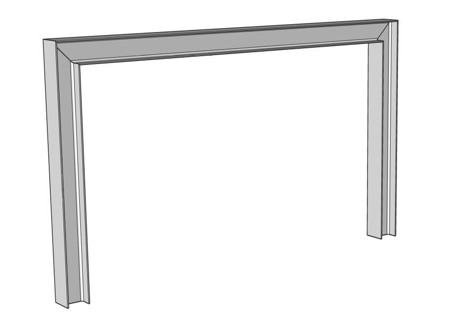
Draw a column with a height of 3000 mm. Don’t exit the command and draw a
connecting beam with a length of 5000 mm horizontally. Now, add another
column at the end of the beam. The height of this column is also
3000 mm.
Note: Make sure you turned the profiles in
the right way.
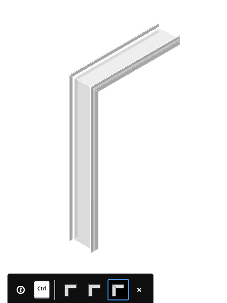
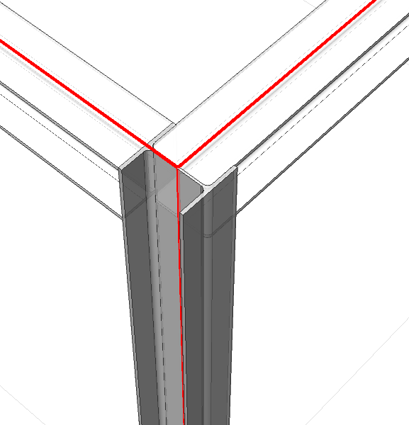
Select the 3 beams and select Connect Structural in
the ribbon or select the command from the Quad. You will be able to choose
which connection you prefer. Choose the L-connection option and press enter.
Your entities are now connected.
In the ribbon, make sure you enable the Display sides and
ends and Prioritize selection of
Faces. You can find them in the
Structural/MEP –
View tab or set the value of DISPLAYSIDESANDENDS
system variable to 1 and SELECTIONMODES system variable to 2.
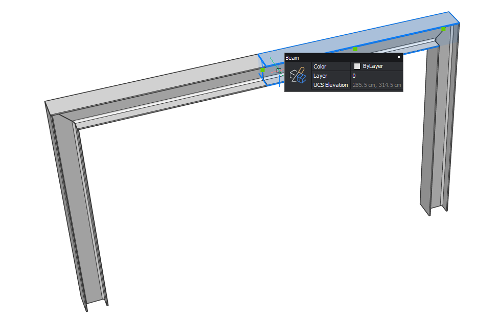
Check if the profiles are correctly classified as
Beam and Columns.
Launch the SLICE command and slice the beam in the middle.
You will be
prompted: Slice along axis? Press Enter to accept the default option
(Yes).
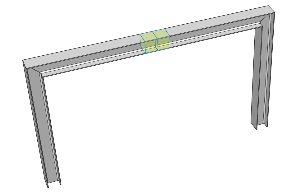
Select the midpoint of the beam and press Enter. Your beam is now sliced
into two beams.
Select the 2 ends of the beams in the middle of the structure. They will be
highlighted in yellow.
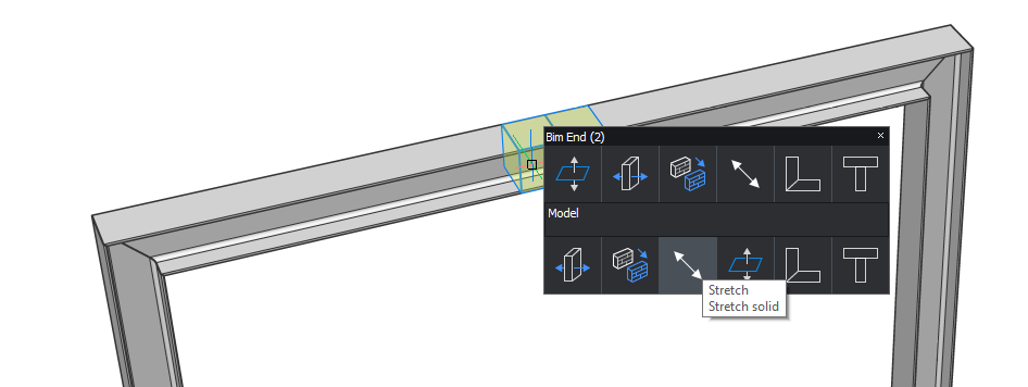
Quad select the BIMSTRETCH command in the Model
tab.
Hover orthogonally upwards, enter a height of 2000 mm and press Enter to
accept.
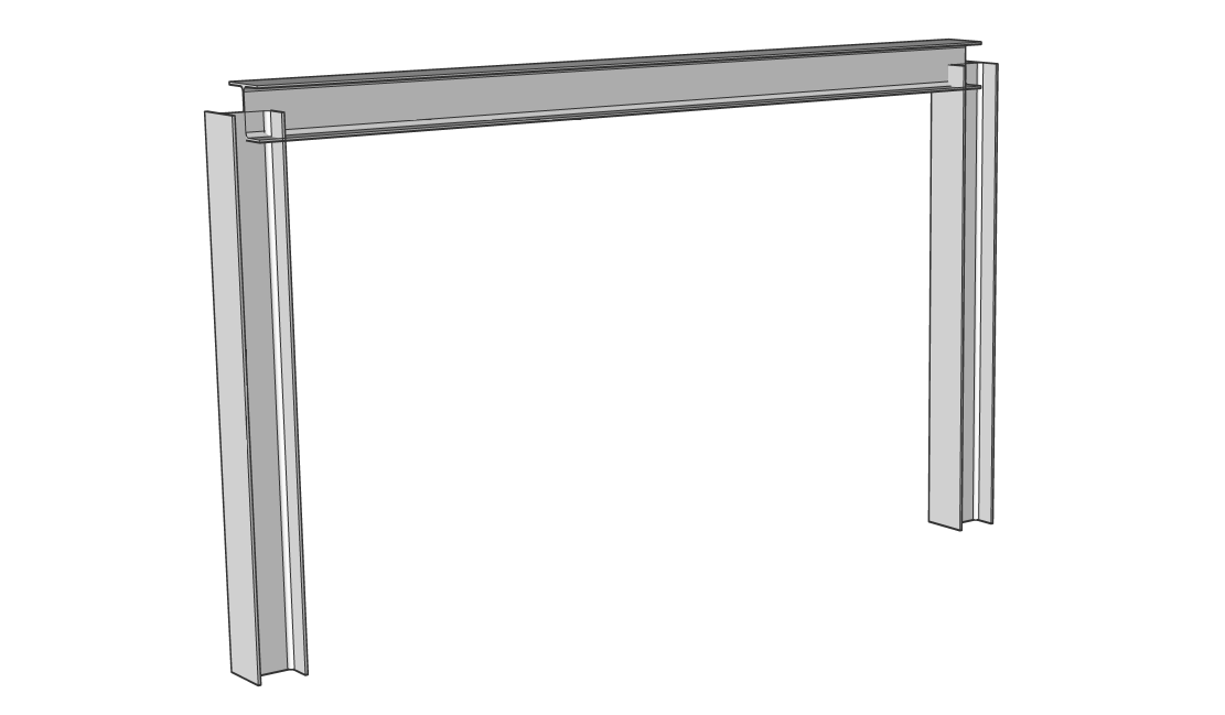
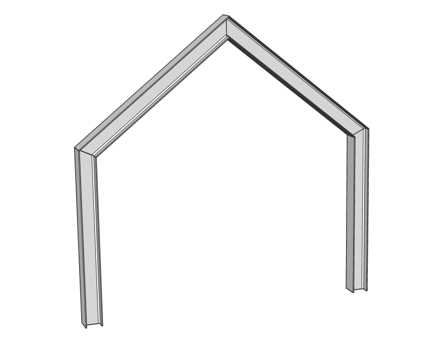
The result should look like this.
As you can see, the connections between the profiles are
automatically adapted to the new angle between the entities.
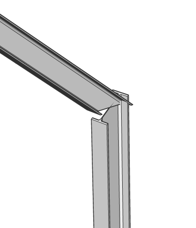
Note: If you would only have selected one of the
two side-ends in the middle of the beam, the connections on the
side that was not selected won’t be included in the stretch and
will look like this: