DmExtrude
Commands
DMEXTRUDE
About

For more information about this command, visit the Command Reference article DMEXTRUDE.
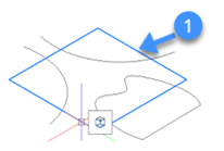
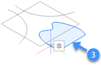
The following illustration shows the selected entities to be extruded.
Procedure: using DMEXTRUDE in solid mode
- Hover the cursor over an entity or sub-entity in the drawing area.
- Select the Extrude tool in the
Model tab from the Quad.
You are prompted: Specify height of extrusion or set [Auto(subtract or create)/Create/Subtract/Unite/Both sides/Taper angle/Direction/Limit] <Auto>.
- The “DmExtrude Hotkey Assistant” appears at the bottom of the screen with a
set of extrusion options.Note: The default mode is indicated by a blue frame.
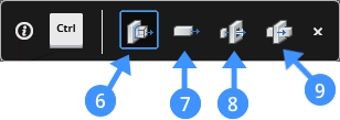
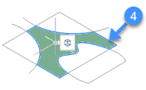
- Auto (6): The result of the auto option depends on the
extrusion direction of the 3D solid and the value of the
DMEXTRUDEMODE system variable value. Note: By default, the value of
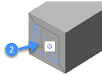
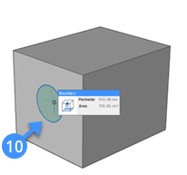
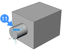
the DMEXTRUDEMODE is set to “3”. The following illustration shows
the extruded entity from the main solid while the default value is
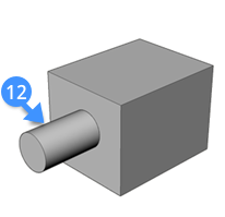
set to “3”. When you highlight an entity (10) and extrude it to the
outward (11), a new volume is added (12) to the main solid
model.
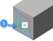
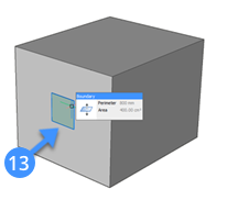
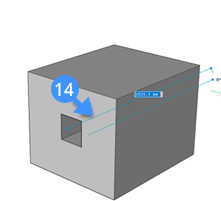
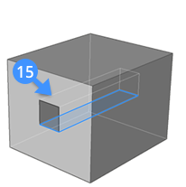
The following illustration shows the subtracted entity from the main solid. When you highlight an entity (13) and extrude it to the inward (14), a volume is subtracted (15) from the main solid.
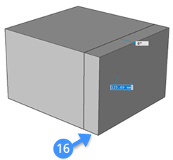
- Create (7): Regardless of the extrusion direction, a new
volume is created (16) from the existing solid.
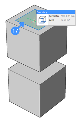
- Subtract (8): The 3D solid is subtracted from each
interfering existing solid.
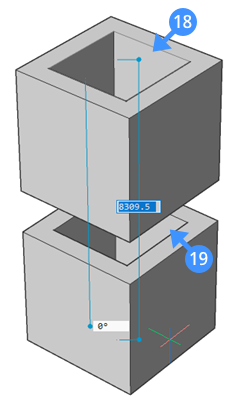
The following illustration shows the subtracted solids (18,19) using the highlighted boundary (17).
- Unite (9): The new volume is unified with each interfering
existing solid.
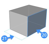
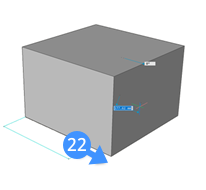
The following illustration shows the before and after when using the extrusion tool unite option. The solid surface is highlighted (20) and the distance between the left and right face is shown with the aligned line (21). The new volume is unified (22) with the first solid.
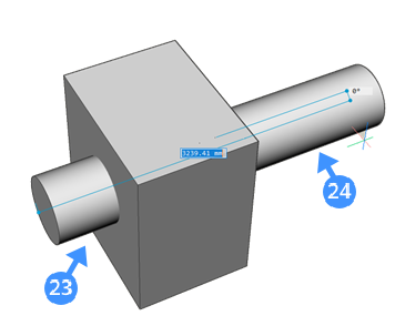
- Both sides: New symmetric volumes are created (23), (24) in
both directions from the main solid.
To create symmetric volumes from the existing solid, type “B” on the the Command line which corresponds to Both sides option of the Extrusion tool.- Select one of the available options to operate the extrusion function on your solid.
- Next, move the cursor in the desired direction to specify the extrusion direction. The selected entity or sub-entity is extruded dynamically.
- Define the height of extrusion by specifying a point in the drawing, entering a value in the dynamic dimension field or choose the limit option.
- Press Enter or right-click to accept the extrusion from your existing solid.
- Auto (6): The result of the auto option depends on the
extrusion direction of the 3D solid and the value of the
DMEXTRUDEMODE system variable value. Note: By default, the value of
the DMEXTRUDEMODE is set to “3”. The following illustration shows
the extruded entity from the main solid while the default value is
set to “3”. When you highlight an entity (10) and extrude it to the
outward (11), a new volume is added (12) to the main solid
model.
DMEXTRUDE in Surface Mode

For more information about this command, visit the Command Reference article DMEXTRUDE.
Procedure: using the extrude tool in surface mode
- Move the cursor over an entity or sub-entity in the drawing area.
- Select the Surface Extrude tool in the
Model tab from the Quad.
You are prompted: Specify height of extrusion or set [Auto(subtract or create)/Create/Subtract/Unite/Both sides/Taper angle/Direction/Limit] <Auto>.
- The “DM Extrude Surface Hotkey Assistant” appears at the bottom of the
screen with a set of surface extrusion options.
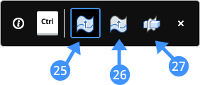
Note: The default mode is indicated by a blue frame.- Auto (25):Select either a surface or the face of a solid element. When the surface’s edge is used as a contour for extrusion, the created surface is stitched with the base surface. When the surface’s face is used for extrusion, the surface results in not stitched with the base surface.
- Create (26):Create new surfaces.
- Slice (27):Cut through solids with the extruded surface. This option is much like the SLICE command.
- Select one of the options and move the mouse to give the extrusion direction, entering a value in the dynamic dimension field.
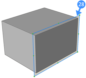
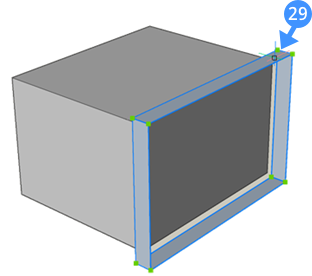
- Press Enter or right-click to accept the extrusion for the surface.The following illustrations show the created surface (29) by extruding the selected 2D entity (28) in the drawing.