Standard Mechanical Components
Overview
Use command COMPONENTSPANELOPEN.
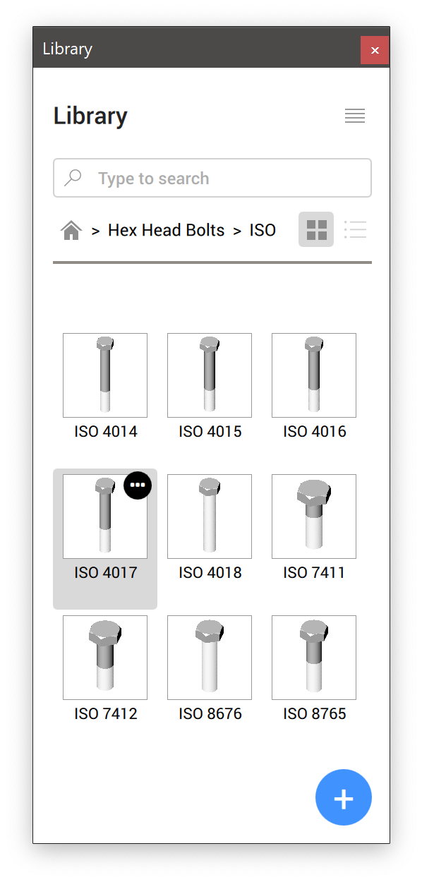
BricsCAD comes with a library of more than 1,000 standard mechanical parts available in more than 170,000 different sizes. They are available in the Library panel, and can be drag-and-dropped from the library into your assembly. You can adjust the parameters in the Properties panel, which temporarily lists parameters of the component being inserted. After insertion, parameters can be edited in Mechanical Browser and the Properties panel.
- Standard Parts
- Holes
- Sheet Metal
Standard Parts (Hardware)
- Fasteners, such as bolts, nuts, and washers.
- Machine Parts, such as bearings, and sprockets.
- Piping, such as pipes, elbows, and flanges.
- Structural Shapes, such as beams, channels, and bars.
The content of each subcategory is structured by type, subtype, and standards.
- Thread representation (THREADDISPLAY) is used to represent (or not to represent) a 3D thread for bolts and nuts. This setting allows to decrease the memory consumption and increase the performance for large assemblies
- Maximum number of sprocket teeth (GEARTEETHNUMBER) is used to limit the number of teeth for sprocket wheels (available under Standard Parts / SPROCKET). This setting allows to decrease memory consumption and increase the performance.
Standard representation of thread in drawing views
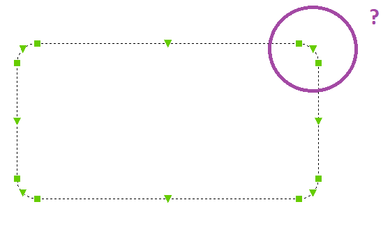
Drawing views of your assemblies, generated with the VIEWBASE command, contain thread annotations for standard parts as thin lines for side views, and as a 270-degree thin arc for top/bottom views.
Holes
The Holes category contains a parametric library of standard holes, such as slots, counterbores, and countersinks.
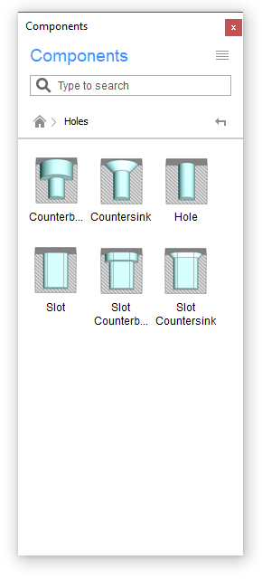
There is also a subcategory of threaded holes, represented in drawing views.
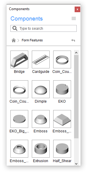
Sheet Metal Form Features
The Sheet Metal category contains a parametric library of sheet metal form features, such as bridges and embosses.
Place a standard component into the current drawing
- Choose a category.
- Choose a standard.
- Select a type.
- Click on the desired standard component.
- Edit the parameters in the properties panel.
- Click in the drawing area to insert the selected component.
Create your own standard component
Use command BMCREATECOMPONENT to create your own standard parts and add them to Components panel.
Control the display of threads
- Open the Settings dialog box.
- Find the Thread representation variable (THREADDISPLAY).
- Enable the setting.
-
If applicable, update the document to make threads appear on existing
parts:
- Temporarily set the Assembly components updating mode (BMUPDATEMODE) to [1] Update all components.
- Use command BMUPDATE to update the document.
- If applicable, return the Assembly components updating mode (BMUPDATEMODE) to the previous value.
Control the number of sprocket teeth
- Open the Settings dialog box.
- Find the Maximum number of sprocket teeth variable (GEARTEETHNUMBER).
- Set the value to be sufficient for used sprockets (500 is
recommended).
Note: Larger values slow down the update of standard sprockets. If the value is smaller than the required number, only that number of sprocket teeth displays.
-
If applicable, update the document to make sprocket teeth appear on existing
parts:
- Temporarily set the Assembly components updating mode (BMUPDATEMODE) to [1] Update all components.
- Use command BMUPDATE to update the document.
- If applicable, return the Assembly components updating mode (BMUPDATEMODE) to the previous value.