Note: For a detailed explanation about
BIMQUICKDRAW, read the article Quickdraw in BricsCAD Shape
article.
About the Polysolid tool
The POLYSOLID command allows you to create wall solids by
selecting a start point, an endpoint and entering a height.
Procedure: Create a simple wall
Launch the Polysolid command:
Click the Polysolid icon in the toolbar
Type POLYSOLID in the command line.
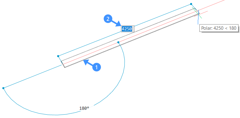
Select a start point, the footprint (1) of the wall is displayed
automatically.
Move the cursor in the desired direction, the current
length value is displayed in the length dynamic entry field (2).
Select an endpoint or enter a value in the dynamic input field and press
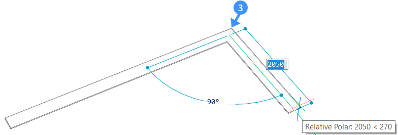
Enter key. The footprint (3) of the adjacent wall
is displayed. Select a new endpoint or enter values in the dynamic input
field to create adjoining wall segments.
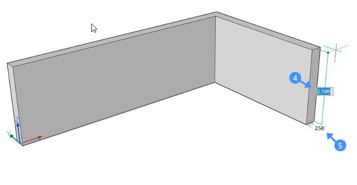
Press Enter once more or right-click. The height of
the wall is displayed dynamically in the height field (4). Here, you can
change the default height of the wall. To change the width of the wall, use
the width field (5). You can switch between the two dynamic input fields by
pressing Tab key.
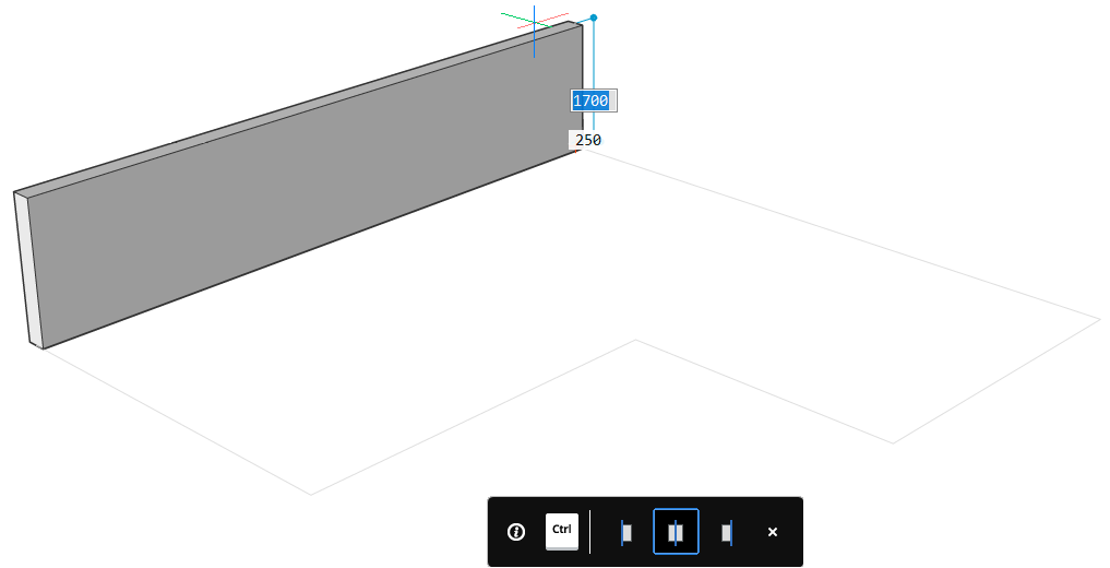
To change the justification of the wall hit CTRL
while the ’Polysolid justification Hotkey Assistant widget‘ appears at the
bottom of the screen.
Note: The width and height of the previous wall
will be the new default values of the next Polysolid.
Procedure: Using an existing 2D plan to create walls
Launch the POLYSOLID command.
Type E in the command line or select Entity in the
prompts menu.
Choose a 2D linear entity which will be the Polysolid base. Lines, open and
closed polylines, arcs, circles, ellipses, elliptical arcs, and splines are
accepted as a polysolid base.
Move the solid up or down and left-click to set the height of the wall,
enter a value in the dynamic input field or right-click to accept the
default value.
The current width of the wall appears in the Width
Field. Press Tab switch between the
Height and the Width field.
The Hotkey Assistant appears and displays the
possible justification options. Press CTRL to cycle
through the wall justification options.
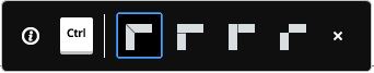
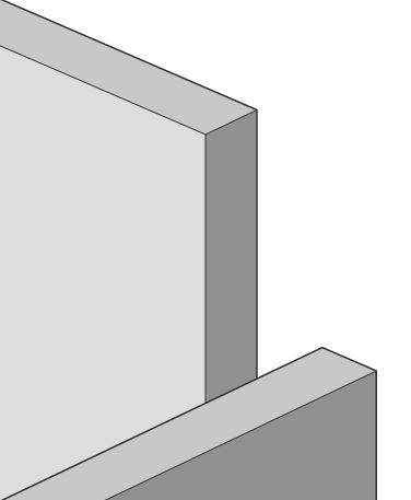
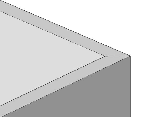
Procedure: Creating L-connections between two walls
Launch the LConnect tool, by typing
LConnect in the Command line and press Enter.
Select the two wall elements you want to connect.
Note: When two walls intersect, a mitered
connection will be created by default.
Change the layout of the wall connections using the ‘LConnect
HotKeyAssistant widget’.
The selected connection type is indicated by a
blue frame.
The connection can be (from left to right) a bisector L-connection
, L parallel type 1 , L parallel type 2 or a disconnection.
Press
Enter to accept the current connection type
or press CTRL to cycle through the possible
connection options.
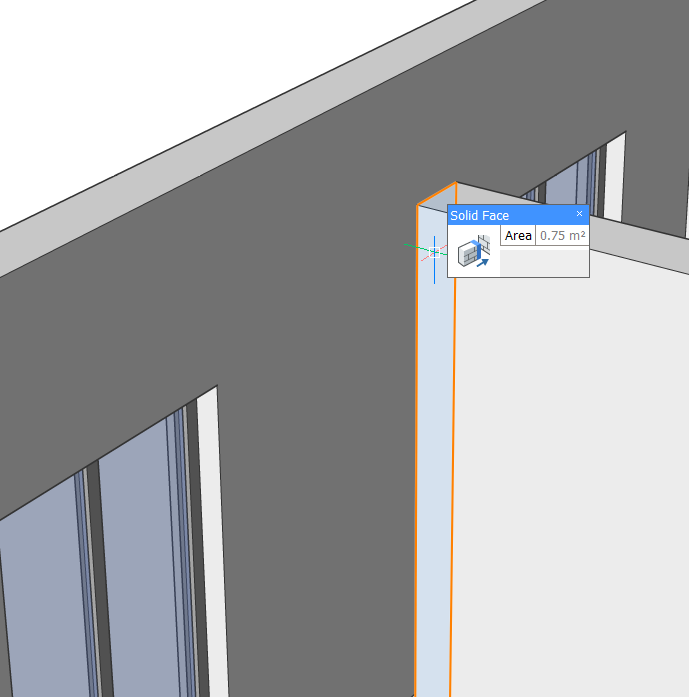
Procedure: Creating T-connections between two elements
Launch the TConnect command.
The tool allows you to
connect the minor face of a wall to the major face of another element or
wall. This tool can be used to connect the top face of a wall to a roof,
the bottom face to a slab or side face of a slab to a wall.
Select the faces of the objects that you would like to connect and press
Enter.
Select Connect to nearest in the prompt menu.
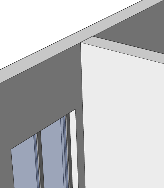
You can also use the Quad menu to create a T-connection
between two walls or other elements:
In the drawing area, highlight the face you want to connect to another
wall.
Use the Connect with Nearest tool from the
Quad.
The Connect with Nearest tool automatically makes a T-connection between the two
walls by extruding the face of the first wall to the face of the other wall.
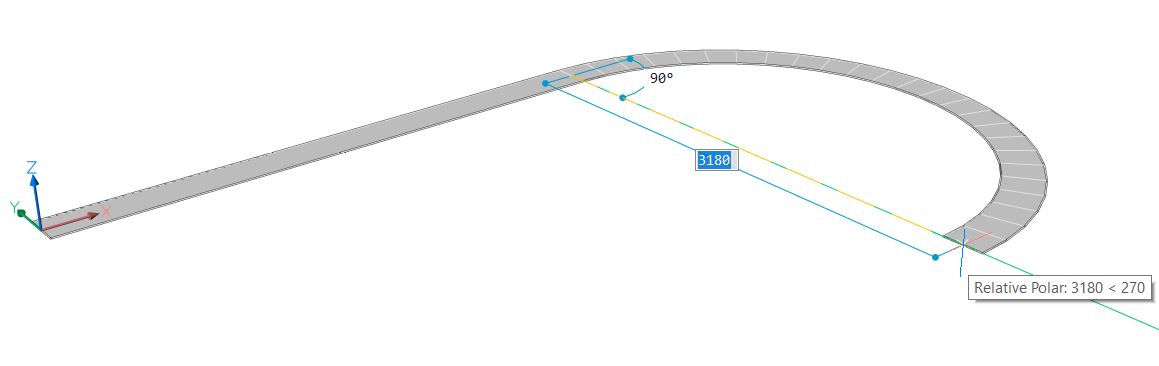
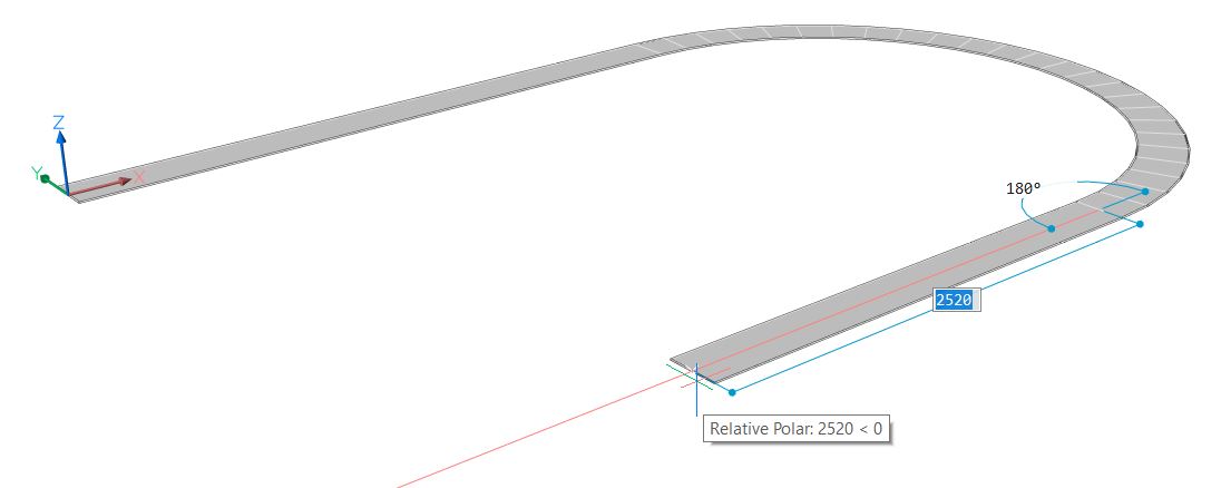
Procedure: Creating a curved wall
Launch the POLYSOLID command.
Select a start point and move the cursor to set the length or click to set
the endpoint.
To create a curved wall, type A and press Enter to choose Draw
arcs or select Draw arcs in the
prompt menu.
Now move the cursor in the desired direction to curve the wall. Enter a
value in the dynamic input field to set the degree and length of the arc.
Press Enter.
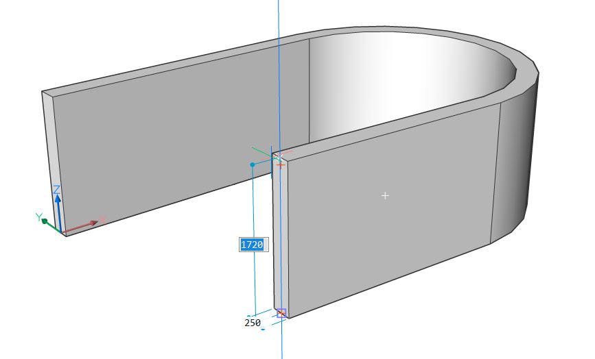
You can continue creating curved, adjoining wall segments by clicking or by
entering values in the dynamic input fields. To go back to drawing straight
wall segments, type L and press Enter or select Draw
lines in the options dialog.
Press Enter once more or right-click. The height of the wall is displayed
dynamically in the height field. Type a value to change the default height
of the wall. To change the width of the wall, use the width field. You can
switch between the two dynamic input fields by pressing Tab.
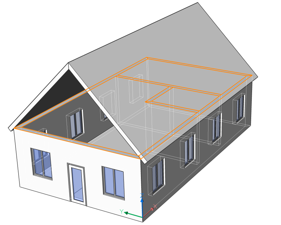
Procedure: Connecting multiple faces of the wall to the roof slab
To select all faces aligned to the current selection, highlight the top face
of one of the walls and click the Select aligned
faces tool in the Select tab of the
Quad.
Launch the Connect with Nearest tool. The top faces
of the wall are attached to the roof.


 Note: When two walls intersect, a mitered connection will be created by default.